Recently, the network coverage area has increased significantly GSM standard 900.Nevertheless, the situation is far from ideal. If in European countries the problem of uncertain reception is practically absent, then most domestic users often encounter it - in country houses, at dachas, etc. And how wonderful it would be to go fishing, hunting, to the village, without losing touch with the outside world! The key to solving this problem is external directional or omnidirectional antennas. True, buying an antenna is not enough - you need to install and configure it correctly. Readers familiar with radio electronics will be able to independently manufacture and configure an antenna operating in the GSM standard. Today we will talk about the types of antennas and how to install and configure them.
Simply put, a mobile phone is a duplex radio station that communicates on different frequencies. There are a total of 124 frequencies in the GSM 900 standard. The phone, like the base station, can operate on any frequency determined by the operator. The base station (BS) transmits and the telephone (MS) receives at frequencies 935.2 - 959.8 MHz. The mobile phone transmits and the base station receives at frequencies 890.2 - 914.8 MHz. The channel from BS to MS is called Down Link, from MS to BS - Up Link. Most operators limit the operating range of a mobile phone from base station- 35 km, which is due to the features of the standard. Let us explain that in a standard configuration network, 8 time intervals (time slots) are formed in one frequency channel: one is service, and seven are conversational. It is in this case that the maximum communication range on each channel is 35 km. However, GSM also provides a non-standard cell configuration, in which the communication range increases by 70 - 100 km (Extended Cell configuration). Unfortunately, with this configuration the number of conversation channels is reduced to 2 - 3, which reduces the network capacity. It is not profitable for the operator to use this mode in and around the city. Sometimes this mode is used on the sea coast to create coastal coverage. Thus, if you have a GSM 900 phone, do not try to establish a connection more than 35 km from the nearest base station. The maximum communication range achieved by me is 34 km. The following factors influence the radio range:
- Location of BS and MS and terrain.
- MS power and sensitivity.
- Power and sensitivity BS.
- Antennas used on MS and BS.
- The will of the Lord God (experienced signalmen joke that this is the main thing).
Typically base stations have a power of 20 - 30 W. Antennas are used either whip or directional. The sensitivity of base stations is -100 dB - 115 dB. The user, of course, cannot change or influence all these parameters. The phone's output power is 0.3 - 2 W, sensitivity - 90 - 105 dB. The sensitivity of a phone is mainly determined by the technologies used to create low noise input devices. If in areas of reliable reception the difference in sensitivity and power between models is almost unnoticeable, then in an area of uncertain reception it can become critical. Often the handset shows the signal level from the base station as 1 - 2 cubes (on the scale), but cannot establish a connection: there is not enough power. And although the ETSI standard regulates the standard output powers for each class of phone, the actual value may vary slightly. Tubes from SAGEM, Alcatel, and Motorola have good sensitivity. And all old phones pass in terms of power, especially Motorola. All phase 2 phones have approximately the same power. As for the terrain, waves travel better on flat terrain and along the river. The higher you are (within reasonable limits), the better signal. The forest sometimes dampens the waves more than urban buildings.
So, you are out of town and want to provide yourself with communications. Climb to the roof, attic, or highest point near the house or location you want. If your phone can catch the network, but at the limit (or unstable), you have every chance to improve the situation by using an external antenna. If the distance to the station is less than 30 km, and the network is not available, also try using an antenna. In the latter case, try to negotiate with the sellers to return the antenna if the experiment fails.
If the signal, although very weak, was still caught, dial any city number to check. If during a conversation, audibility is normal and the interlocutor does not complain about the loss of parts of your speech, it means that the energy of both lines (UL and DL) is balanced and you can use a standard antenna tuned to the middle frequency between the receiving and transmitting frequencies. If the interlocutor disappears from time to time, it is necessary to “strengthen” the downward direction from the base station to your phone. It might be worth looking for a phone with better sensitivity. But if it is difficult to hear you, you should strengthen the direction from your phone to the base station. Already at this stage it is clear that when choosing the type of antenna and its parameters, it is advisable to take into account the operator’s data and reception conditions. In areas of poor reception, interference (noise) is often observed between channels with the same and adjacent frequencies. Unfortunately, the frequency resource allocated to GSM 900 operators in Russia is limited, which is why frequencies from different base stations with the same or neighboring signal strengths are often “visible” in areas of poor reception. Such frequencies create mutual interference that interferes with communication, and at certain signal levels communication becomes completely impossible. If a strong signal from the base station is recorded on the phone screen, but it is not possible to establish a connection, or it is possible, but speech disappears all the time, then you are faced with “strangers”. It is not always possible to “force” a phone to select a different frequency, but a special function of Nokia phones - Netmonitor - allows you to do this.
I encountered a similar problem at my dacha, which is separated from a large city by a fairly open space. The phone received adjacent frequency channels with levels of 70 dB, 73 dB and 72 dB, but the quality of communication left much to be desired. The only thing that saved me was the forced selection of another frequency channel with a lower level - 80 dB. However, with a limited frequency resource, even frequency rescheduling of the network does not always help. However, if your phone does not have Netmonitor, you can use an external directional antenna with a good radiation pattern. All that remains is to make the right choice.
As already mentioned, external antennas allow you to increase the range and quality of communication. For telephones, external whip and log-periodic antennas, as well as wave channel antennas, are mainly used. Let us repeat that in Western Europe there are no areas of uncertain reception. Therefore, directional antennas for GSM 900 terminals are practically not produced. If a manufacturer offers a directional proprietary GSM 900 antenna, it is usually designed to work with operator repeaters.
In the CIS and Eastern Europe, directional antennas are made in a handicraft manner. In addition, there are small factories in the Czech Republic, Poland and the Baltic states. A simple car magnetic antenna has a gain of 1 - 3 dB (1 - 2 cubes on the telephone scale), a wave channel - 7 - 15 dB (depending on the number of elements, build quality and antenna settings), which is already 2 - 3 cubes on the scale , and the log-periodic antenna is 7 - 12 dB. A car antenna is a vertical rod of 3/4, 1/2 or 5/8 wavelength. Even a simple car antenna, raised higher, can improve the situation with uncertain communications. The fact is that when talking on the phone, about 10 - 20% of the energy is absorbed by the user's body, therefore, by raising the whip antenna up, you reduce the influence of surrounding objects on it. I myself have observed how homemade, half-wave and vertical dipoles, raised to 5 m, solved the communication problem. Let us explain how such a dipole is made.
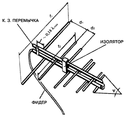
Rice. 1. Vertical dipole
We strip the white RG6U television cable from one end. We get the central conductor and cable braid. We solder a copper wire of any thickness about 8.2 cm long (for the 900 MHz range) to the central conductor and fasten it vertically upward. We solder a second piece of wire of the same length to the braid and fasten it vertically downwards (Fig. 1). We get something similar to the letter “T” laid on its side. (Television uses horizontal polarization, while GSM uses vertical polarization, so just such a dipole is required.) We connect the other end of the cable through an adapter to the phone. Be careful not to short the central core with the braid, otherwise the phone may burn out. Well, in 5 minutes we built a primitive antenna, not inferior in parameters to Chinese automobile ones.
Let me give you a story from my life. Arriving last summer on vacation in Crimea, I discovered that there was no reliable coverage on the base promised by the operator. This meant that I would miss a very important call. A reliable signal was found on the roof of the cottage, but the prospect of sitting there for two weeks did not inspire me. In 5 minutes I found a piece of the required wire (I used aluminum instead of copper). It took another 10 minutes to find a 5-meter piece of television cable from the neighbors. Nokia 7110 has a mechanical switch for external antenna, so I simply plugged the center conductor of the cable directly into the phone jack, and connected the cable braid to the metal rim of the phone's outer jack. I mounted the antenna on the roof of the house and within 10 minutes, to the delight of my family and the envy of my neighbors, I was freely communicating on the phone.
As they say, let's go back to our sheep. First, let's use a car whip antenna ($5 - 10). The main thing here is not to run into too bad quality. Having Netmonitor, it is much easier to check the antenna. When the car antenna is connected to the phone, the signal level should increase by 1 - 3 dB (for example, from -60 dB to -57 dB). As a last resort, the signal should remain the same. If, when connecting an antenna, the signal decreases by 5 dB or more, it is better to refuse the purchase. I would like to note that a good branded car antenna costs $40 and above. However, even among the Asian 10-dollar products there are sometimes some good things. Installed on the roof of your “village”, a car antenna can solve your communication problem. If the gain of the car antenna is not enough, you can turn to others - for example, a common directional antenna - a wave channel. He looks like an ordinary one TV antenna installed on the roof of the house.
The wave channel allows you to get real gain up to 7 - 15 dB with an optimal radiation pattern. But it has a drawback - narrowband. The difference between the reception frequency and the transmission frequency in GSM 900 is 45 MHz, and the entire operating range is 890 - 960 MHz (70 MHz band). It is difficult to achieve linear or near-linear performance over such a wide range. Therefore, it is advisable to make a wave channel depending on the frequency of the operator and the specific location and, depending on the situation, shift the resonance to the frequency of the ascending or descending directions. For greater broadband, you should use only a loop vibrator, matching it with a cable - for example, with a balun; You should also limit yourself to a small number of elements, say 3 - 12, since if there are more of them, it will be difficult to tune the antenna without equipment, in addition, the operating range of the antenna is narrowed.
I had to deal with many handmade wave channels. I state: in most antennas the gain was less than 7 dB, some had resonance at frequencies of 700 - 800 MHz instead of the GSM range and a standing wave ratio of more than 3 (during transmission, this can easily damage the output stage of the phone). Professionally manufactured and customized homemade antennas rarely met.
Now the next step is log-periodic antennas (they can also be found on the radio market). Compared to the wave channel, they have a wider operating range. Therefore, such antennas are less critical to the accuracy of manufacturing and tuning. The actual gain here reaches 10 - 14 dB. Theoretically, if necessary, you can connect 2 wave channels, one tuned to the receiving frequency, the other to the transmitting frequency, but this is already too complex a system.
In the 900 MHz range, the issue of cable selection becomes paramount. Domestic television coaxial cables can only be used to a limited extent (the attenuation of more than 30 dB per 100 m is too high). Of the available imported samples, RG6 is a suitable double-braided coaxial cable. You will find it in any store. The attenuation is 20 - 24 dB per 100 m (tested experimentally). Industrial pins car antennas typically include RG59 cable with an attenuation of 28 dB at 100 m. A wave channel antenna with a gain of 12 dB and 10 m of RG6U cable give a total gain of 9.6 dB, and at 20 m - 7 dB.
Most phones have a connector for an external antenna. In addition, for each type of phone there is a so-called antenna adapter (about $5), it connects to the specified connector and is a short piece of cable, on one side of which there is a specific telephone high-frequency connector, and on the other - a standard RF connector. Typically, the attenuation in the antenna adapter does not exceed 1 dB. When purchasing an antenna adapter, make sure it is functional. When you plug the adapter into the phone, the antenna built into the phone is turned off and the output stage switches to the adapter. In other words, if you simply connect the adapter to the phone, the signal on the phone's dial should drop slightly. Then you connect an external antenna to the adapter and the signal increases. If everything goes this way, then the adapter is working.
So, you bought an antenna and connected it to the cable and to the phone. We climbed to a high point and began setting up the antenna. Place the phone so that the screen is visible. As already mentioned, when setting up an antenna with Nokia devices, it is best to use the Netmonitor function. In most other phones, you can enter a special code and open the service menu, which allows you to see the receiving level of 6 - 8 frequencies received by the phone in descending order, frequency numbers, distance to the base station, percentage of errors in the channel, etc. If Netmonitor is available, we will guide you by signal level in decibels (remember that the signal is stronger when the level value in decibels is lower). If it is missing, we will tune according to the standard signal scale.
Since the antennas of GSM 900 base stations are vertically polarized, the wave channel should be placed vertically. When adjusting antennas, please note that the receiving signal level displayed on the phone changes with a delay of up to several seconds, so the antenna should be rotated slowly and discretely. If you know the direction to the nearest city, start there. Slowly turn the antenna horizontally. If a signal is found, your task is to find the direction from which the signal comes with the maximum level. If there is no signal, slowly turn the antenna horizontally until it appears. Remember that every meter of antenna installation height can be decisive. If no signal is found, try moving a few meters to the side and searching again. Maybe you'll get lucky. It is not advisable to use a cable between the antenna and the telephone longer than 30 m: in this case, almost the entire signal is lost in the cable.
Finally, we present the dimensions of a homemade log-periodic antenna for the range 850 - 950 MHz (Fig. 2). Parameters: gain - 8.3 dB, characteristic impedance - 60 Ohms.
External GSM antenna - a device that picks up a mobile operator signal from a base station in a certain frequency range, amplifies it and transmits it via coaxial cable to the repeater, which, in turn, amplify this signal.
External GSM antennas VEGATEL support operation in several standards cellular communication- GSM-900 (900 MHz), GSM-1800 (1800 MHz), EGSM (about 900 MHz), CDMA (3G, 2100 MHz).
Features of GSM VEGATEL antennas
Cellular signal amplification antennas have different power factors from 7 dB to 20 dB and provide pre-amplification cellular signal, before it gets into the amplifier. This is necessary in order to compensate for the loss of signal power while passing through the cable.
Other uses of such antennas are known. They connect directly to cell phone via the appropriate connector. Sometimes this is enough for confident reception and conversation. The only negative is that the subscriber becomes tied to the antenna.
To get the most out of your cellular booster antenna, you'll need to position it correctly - pointing toward the base station. mobile operator. They are usually installed on the facade of a building or on a mast. Thus, the incoming cellular signal will be the maximum possible at this point in the area. After this, the signal is transmitted to GSM repeater, where it is amplified, transmitted to the internal antenna. As a result, the subscriber receives a zone of high-quality reception, where the operation of the cellular network is satisfactory, which solves the problem of poor communication. This system of cellular signal amplification is widespread throughout Russia and is absolutely legal.
Antennas to boost the 3G modem signal
Our company produces antennas designed for connection to USB 3G modems. Such antennas have their own gain, thanks to which the 3G signal reaches the modem already amplified. Using such an antenna to strengthen the 3G modem signal, you can increase the speed mobile internet several times.
Everyone who only has access to this type of Internet has encountered the problem of slow 3G Internet. You can solve this problem by using an amplifier antenna for a 3G modem. The connection to the modem is simple - through the pigtale connector, which is found on every 3G modem.
To buy the right antenna for a GSM modem, you can call us, and our managers will help you with your choice and give professional advice.
Advantages
Outdoor antennas for amplifying cellular signal VEGATEL are made of corrosion-resistant materials that have a degree of protection against external factors IP40 and have a high wind load value, which guarantees long-term and efficient operation.
When choosing a phone, we rarely pay attention to the characteristics of the antenna installed in it (and they are usually not brought to the fore, hiding somewhere on the penultimate page of the instructions) - as a rule, almost all phones are capable of providing a normal level of communication in normal urban conditions . But everything changes when you have to use the phone in conditions of uncertain reception - for example, outside the city. Sometimes the situation can be corrected only by connecting an external antenna to the phone. I propose to talk together about cell phone antennas, discuss their types, consider the most important characteristics and rules for their use.Types and features of antennas
To a first approximation, antennas for cell phones can be divided into two types - antennas built into the cell phone and plug-in antennas. There is another class of devices - repeaters - complexes of several antennas (at least 2) and an amplifier. Built-in antennas are divided into internal, external whip and external retractable antennas. The latter are irrelevant for the modern GSM devices that we use today, but the first two types are worth dwelling on in more detail.
Whip antennas
In the recent past, the main type of antennas for mobile phones were external whip antennas (Helical Antenna - helical antennas). Such antennas can still be found today, but only a few phones are equipped with them. The efficiency of such antennas can exceed 90%. In the case of antennas, efficiency is the ratio of the radiation resistance to the total resistance of the antenna system (efficiency can also be calculated as the ratio of the radiated power to the supplied power). The higher the efficiency, the less energy is lost in the antenna system - for example, if the antenna efficiency is 70%, then 70% of the power supplied to it is radiated, and 30% is lost in the form of thermal radiation. Whip antennas have a circular radiation pattern (usually it is uneven, but close to ideal). The radiation pattern is graphic image radiation or antenna sensitivity, usually a diagram with polar coordinates. When constructing such a diagram, it is assumed that the antenna is located in the center of the diagram. As a rule, radiation patterns are constructed in the horizontal plane. They have characteristic lobes - usually the longest lobe (that is, the one in the direction in which the antenna emits greatest number energy) is called the main one.
Another one important characteristic antenna is the gain of the antenna. It is usually measured in isotropic decibels dBi. The higher the gain, the better. A passive antenna (this applies to external connected antennas), that is, an antenna not equipped with a special amplifier, does not amplify the signal, but only redistributes it in space, the highest level of gain is in the direction of the main lobe of the radiation pattern. Among modern models In phones, you can hardly find a device that allows you to change antennas, but in the past this was quite common.
Cell phone whip antenna
Having discussed external antennas, we move on to internal ones.
Internal antennas
Internal antennas (Planar, PIFA Antenna - planar antennas, microstrip antennas) are usually built inside the phone body. A phone with an internal antenna has no protruding parts - owners of phones with protruding antennas usually complained that these antennas rip their jeans pockets, get caught on everything, and sometimes break. From a cosmetic point of view, the absence of protruding antennas makes the phone more attractive, although some believe that a phone should have a protruding antenna - this is usually a matter of habit. There is information that internal antennas are less efficient (the best examples do not reach 70% efficiency) - however, this is quite difficult to verify. Further, internal antennas, unlike external ones, are usually directional antennas. As a rule, the main directivity lobe of such an antenna comes from back wall device, that is, directed from the head of the person talking on the phone. This does not interfere with the work in the reception area, but when you are too far from the base station, or something interferes with the normal passage of the signal, you may encounter some strange things - for example, if you put the phone to your right ear, you can talk normally if you left - no. It's all about the direction of the antenna - if the main directional lobe is directed towards the base station, reception is reliable, if not, communication problems begin.
Another disadvantage of internal antennas is that for each model (or for each group of models) of the phone such an antenna has to be developed separately - taking into account the peculiarities of the arrangement of elements inside the phone, the features of the case, and so on. However, apparently, this issue is being successfully resolved - at least the number of new cell phones that periodically appear on store shelves forces us to draw such a conclusion.

inexpensive, equipped with a built-in antenna
Built-in antennas can be located in the upper part of the device, however, sometimes they are placed somewhere in the center of the phone, or even in the lower part (as, for example, in the famous telephone). When talking, it is undesirable to cover the antenna with your hand - this leads to a deterioration in communication conditions and the phone, in order to ensure normal conversation conditions, is forced to increase the transmitter power. As a result, the cell phone battery runs out faster, and its owner is exposed to increased radiation. And although the question of the harm or harmlessness of the effects of cellular radiation on the human body is still open, we must not forget that this impact is also in our interests so that it is as weak as possible.

PIFA antenna for GSM range from Antennovation
Internal planar antennas are also used, for example, to implement Bluetooth and Wi-Fi communications.

Internal Bluetooth antenna
A special class of devices consists of external antennas for cellular phones and other devices for improving communication quality.
Connectable antennas
External antennas for cell phones are relatively rare. The fact is that most users have enough built-in antennas. In addition, fewer and fewer phones have a connector for connecting an external antenna - manufacturers do not want to spend money on a part that is not used very actively. To connect an external antenna to a telephone, a coaxial cable with an appropriate connector is usually used. As a rule, external antennas are directional antennas, therefore, for example, when installing one in your dacha, you need to accurately find the direction of the antenna to the base station.
Much more interesting than ordinary external antennas are the so-called repeaters - devices that consist of an external antenna (usually highly directional) that receives a signal from a base station and emits a signal, a signal control and amplification device and one or more internal antennas (usually - omnidirectional, although there may be options) - that is, antennas located indoors. With the help of repeaters, you can organize stable mobile communications in rooms with uncertain signal reception and even in places where cell phones do not work under normal conditions (for example, in basements).
The advantages of systems with a repeater over plug-in antennas are that they do not limit the freedom of movement of a person with a cell phone, without requiring a cable to be connected to the phone.

External antenna Yagi-10

Internal antenna

"Home" repeater with two antennas
Perhaps the main disadvantage of repeaters is their relatively high price. So, in the initial version (external antenna, repeater, internal antenna), this design is comparable in price to a good cell phone, but more advanced solutions can cost more - about several thousand dollars.
conclusions
As you can see, cell phone antennas are interesting and complex devices. They are constantly evolving, although recently they have received very little consumer attention, focusing on additional features mobile phones. However, the antenna is very important. I wish you a stable connection.
comments powered by Disqus. ,
The first designs of cell phones used telescopic antennas, and somewhat later - small-sized antennas. In cell phones you can find such small-sized antennas: spiral, vibrator and low-profile.
If the parameters of a helical antenna are selected appropriately, it is very effective. The non-directional radiation mode is used, which is realized when the helix diameter D is significantly less than the wavelength. In this case, in the plane of the turns, the antenna radiates evenly in all directions, and in the plane coinciding with the axis of the spiral, it has the shape of a figure eight.
Helical antennas are a spiral covered with a polymer shell on a dielectric rod. There are models with a spiral enclosed in a rubber casing, “in flexible design”. Helical antennas have a physical length of 1/12 with a quarter-wave electrical length. With a further decrease in physical length, losses increase sharply. The unsatisfactory performance of the helical antenna in portable radiotelephones in 800...900 led to the fact that the developers complicated it, achieving gains compared to a single helix. A sophisticated helical antenna consists of two helices: a primary one, rigidly mounted on the body, approximately 2 cm long, and a secondary one, approximately 10 cm long, which is located inside the body of the radiotelephone. When extended, the secondary spiral becomes the main emitter.
The shrinking size of cell phones has forced the use of vibrator and coil emitters to shift away from use and toward low-profile designs. Microstrip antennas and F-shaped antennas are known as typical low-profile antennas and are widely used in cordless telephones. The dimensions of the wearable telephone allow the antenna to be placed on the front or side of the case.
In modern devices, the antennas are made in the form of a short stationary pin, which is installed inside the case and is almost invisible. Changes in the design of the antennas used are associated, first of all, with an increase in the operating frequency, as well as the requirements for ease of use. Reducing the size of the housing and, accordingly, the size of the antenna leads, as a rule, to a decrease in the efficiency of its operation during transmission and reception. Therefore, the use of small-sized cell phones is justified only where the cellular network mobile communications is quite developed and has powerful base stations.
Experience shows that in most cases the best antenna is a standard one. If necessary, it makes sense to purchase a stationary or car antenna. A stationary directional antenna is installed on the street in the same way as a television antenna and is directed to the nearest base station. Such antennas are used to improve the quality of communications in buildings and basements, as well as to provide communications outside the reception area in the suburbs.
In cellular communications, a classic half-wave antenna, which does not depend on near-field losses, is usually used as a remote antenna. Most modern mobile phones use quarter-wave vibrators of various forms, in which the design of the device itself serves as the lower part of the radiating structure for the antenna - as it were. The measured radiation flux density of a mobile phone can be several tens of percent of the rated power and depends on how the user’s hand is positioned with the device near the ear (working position of the device).
The main losses in antenna efficiency in the operating position of the device are called “near zone losses”. These losses are determined mainly by two factors: the resulting ruggedness of the radiation pattern and radiation power losses per unit of user body weight and, naturally, for a large subscriber, the near-field losses are greater. Being far from cities, cellular users often encounter uncertain reception from base stations. The way out of this situation is to use an external antenna to operate the phone. Let's look at some features of radio communications in the widely used standard. The GSM-900 standard contains only . A cell phone, like a base station, can operate on any frequency determined by the operator. Transmission from the base station (BS) to the phone (MS) is carried out on some frequencies (935.2...959.8 MHz), while transmission from a cell phone to the base station is carried out on others at frequencies (890.2. ..914.8 MHz). The link from the base station (BS) to the mobile station (MS) is called Down Link, and from MS to BS is called Up Link.
Operators usually limit the operating range of a mobile phone from a base station to 35 km, which is due to the peculiarities of the standard. If in a standard configuration network, 8 time intervals (time slots) are formed in one frequency channel: one for service and seven for conversational ones, then in this case the maximum communication range on each channel is 35 km. In GSM you can also use a non-standard cell configuration. In this case, the communication range increases to 70... 100 km (Extended Cell configuration), and the network capacity is reduced to 2-3 channels.
This mode of operation is unacceptable for urban conditions, as the number of cellular network subscribers is decreasing. This mode of cellular communication is sometimes used on the sea coast to create coastal coverage.
Summarizing what has been said, we can conclude that if you have a GSM-900 phone, for normal operation of a cell phone you should not move more than 35 km from the nearest base station, otherwise communication with it will be difficult or simply impossible.
The radio communication range is known to be influenced by the following factors: BS and MS location and terrain. Cell phone power and sensitivity (MS). Cellular base station (BS) power and sensitivity. Antennas installed on MS and BS. Time of year and weather conditions.
Typically base stations have a power of 20...30 W. Antennas are used either whip or directional. The sensitivity of base stations is minus (100...115) dB, while the phone's output power is 0.3...2 W and the sensitivity is minus (90...105) dB. The sensitivity of a phone is mainly determined by the technologies used to create low noise input devices.
If in areas of reliable reception the difference in sensitivity and power between different models of cell phones is almost unnoticeable, then in an area of uncertain reception it can become critical. Often the handset shows the signal level from the base station as 1-2 cubes (on the scale), but cannot establish a connection: there is not enough power. And although standardization regulates the standard output powers for each class of phone, the actual value may vary slightly. Tubes from Sagem, Alcatel, and Motorola have good sensitivity. And all old phones pass in terms of power, especially Motorola. All phase 2 phones have approximately the same power.
When setting up a radio communication session, it should be taken into account that radio waves propagate better on flat terrain and along the surface of a river, while in the forest the transmission of waves is worse than in the city. The radio signal travels or is received better if you are at a higher altitude than the surrounding area. It happens that during a communication session you are heard well, while the interlocutor disappears from time to time. To correct the situation, you should replace your phone with a device with greater sensitivity. If you are at such a distance from the base station that the phone’s reception of the network signal is limited or unstable, then to improve radio communication you should try connecting an external antenna to the phone.
In areas of poor reception between channels with the same and adjacent frequencies, interference is often observed. This is due to the limited frequency resource allocated to operators. And in this regard, in an area of uncertain reception, signals from different base stations are often recorded, having the same or adjacent signal frequencies.
Such signals create mutual interference that interferes with communication, and at certain signal levels, communication becomes completely impossible. If a strong signal from the base station is recorded on the phone screen, but it is not possible to establish a connection, or it is possible, but speech disappears all the time, then you are faced with “strangers”. In such a situation, the phone is not always able to select a different frequency, so if you have Nokia phone, then you can try to use the "NetMonitor" function. If your phone does not have the NetMonitor function, you should use an external directional antenna with a good radiation pattern.
SELECTION OF EXTERNAL ANTENNAS
All stationary antennas can be divided into two types: directional and non-directional. As non-directional stationary antennas Half-wave, collinear and solinear antennas are mainly used. Omnidirectional antennas, as a rule, have lower gain compared to directional antennas and are mainly used where it is possible to receive a signal from several base stations. In design and characteristics, they are very similar to car antennas.
There are many types of directional antennas, which differ only in design. The main types of directional antennas used are wave channel, log periodic and planar printed antennas. The wave channel antenna has a higher gain and is easy to manufacture. A log-periodic antenna has a more complex design with the same dimensions as a “wave channel” antenna.
Although a log-periodic antenna has a lower gain, it is more broadband, which allows it to be used over a larger range of radio frequencies. For comparison, we present the gain factors of the most common external antennas for cell phones. A simple car antenna has a gain of 1...3 dB (1-2 cubes on the telephone scale), a wave channel - 7...15 dB (depending on the number of elements, build quality and antenna settings), which is already 2-3 cube on the scale, and the log-periodic antenna - 7...12 dB.
WAVE CHANNEL TYPE ANTENNAS
In cellular communications, the Uda-Yagi type antenna (or “wave channel”) has become widespread as a stationary antenna. This antenna has many varieties, which differ in the number of elements, planes of polarization and the design of individual elements. The antenna for cellular communications is vertical, and therefore its active vibrators, reflectors and directors are installed vertically. "Wave Channel" is still one of the best antennas for radio communication on VHF, as well as television reception. The use of such an antenna can significantly increase the range of a cell phone, allowing communication from places significantly remote from the service area of your operator.
The choice of an external antenna is made based on its main parameters: operating range (frequency range); gain (gain); ; .
The operating range of the antenna must match the frequency range in which your cell phone operates. The gain should be selected as high as possible, the antenna impedance (characteristic impedance) should be equal to 50 Ohms, and the standing wave ratio should not exceed two. All of the above parameters of the antenna are usually indicated in its passport, and if this is not the case, then the store salesperson can provide the necessary information. There are antennas on sale with similar radio technical characteristics from other companies that are less expensive than the above types of antennas. This is due to their low mechanical reliability and poor corrosion resistance. Note that in Western Europe there are no areas of uncertain reception, and therefore directional antennas for GSM-900 terminals are practically not produced. On sale there are only directional branded antennas GSM-900 for working with repeaters (repeaters) of operators.
| Type | Name | Number of elements | Operating range (MHz) | Communication standard | Gain (dB) | Characteristic impedance | SWR |
|---|---|---|---|---|---|---|---|
| YAGI10 | 10 | 890...960 | GSM-900 | 15 | less than 2 | ||
| ACV | Polaris 900 | - | 890...960 | NMT-450 | 5 | ||
| ABV9 | CARANT | 9 | 800...960 | GSM-900, AMPS | 11 | ||
| YAGI7 | 7 | 450...470 | NMT-450 | 11 | |||
| ACV26 | CARANT | 26 | 800...960 | GSM-900, AMPS | 16 | ||
| AGV10 | CARANT | - | 1710...1990 | GSM-1800, GSM-1900 | 8 | ||
| WLP | CARANT | - | 890...960 | GSM-900 | 8 |
Characteristics of industrial directional antennas for cell phones
ANTENNA INSTALLATION
After choosing an external antenna, the next step is to correct installation. The easiest way is to mount the antenna on a vertical pipe several meters high and with a diameter of 30...50 mm, installed on the roof of a house or a hill. The antenna is secured with brackets, brackets, bolts with nuts and other fasteners. It must be remembered that the antenna should be directed towards the nearest base station, and its pins should be positioned vertically. The direction to the base station is determined as follows. Connect the cell phone to the antenna using a cable and an antenna adapter, and then, by rotating the antenna in different directions, record the maximum readings of the signal strength indicator. In this case, hands should be removed from the antenna. The measurement of each reading should last at least 10...20 seconds.
Installing an omnidirectional antenna is somewhat simpler. The antenna pin is installed in a vertical position, as high as possible. The length of the connecting antenna cable should be as short as possible. An RG-58 cable 5 m long, usually used for these purposes, attenuates the signal by almost half. For connecting cable lengths up to 10 m, it is better to use RG-59 cable, which has low losses. For longer lengths, it is better to take an RG-213 cable, its diameter is approximately 10 mm.
If the connecting cable is about 50 m long, a so-called booster should be used to compensate for losses in it. A booster is a pair of antenna amplifiers, one of which works for reception, and the other for signal transmission.
To be able to move around the room and not be tied to the connecting cable of an external antenna, they usually use. The repeater consists of an antenna amplifier (50...60 dB) and transmitters, one of which works to transmit the signal from the operator to the cell phone, and the other transmits the signal from the phone to the base station.
The repeater looks like a small flat box, on one of the small faces of which there is a socket for connecting an external antenna, and on the other there is a connector with an attached small indoor antenna, usually in the form of a flexible pin with a gain of 3 dB. Communication between a cell phone and a repeater is carried out at a distance of up to 30 m. The repeater creates, as it were, one small cell, within the coverage area of which you can move freely. When purchasing a repeater, you need to choose a model that works in the same standard as your cell phone.
It should be noted that several subscribers can use it. From 3 to 6 people can talk simultaneously on their cell phones, depending on the standard and type of repeater, but an unlimited number of users can be in standby mode. Thus, your friends who come to visit you or clients in your office can also use the repeater.
There are times when even using a high gain directional antenna in conjunction with a booster or repeater does not produce any results, and there is no connection no matter what you do. There may be several reasons, but the two main ones are: you are in the so-called radio shadow zone or you are too far from the coverage area of the nearest cellular operator. Signal high frequency range cellular communication represents waves of very short length, which propagate mainly in a straight line and, meeting an obstacle on their way, they are either reflected from it or attenuated in its thickness.
In order to get out of the radio shadow zone, it is tedious to raise the antenna as high as possible, that is, install the antenna on a higher mast. The domestic industry produces several types of masts, ranging in height from 7 to 30 meters. If in this case the connection with the operator cannot be established, then you need to buy a satellite phone.
CABLE AND ANTENNA ADAPTERS
In the 900 MHz range, the issue of cable selection becomes paramount. Domestic television coaxial cables can only be used to a limited extent (the attenuation of more than 30 dB per 100 m is too high). Of the available imported samples, RG-6 is suitable - a double-braided coaxial cable. You will find it in any store. The attenuation is 20...24 dB per 100 m (tested experimentally). The cable length between the antenna and the telephone should be no more than 30 m to reduce signal loss.
Industrial automotive whip antennas typically include RG-59 cable with an attenuation of 28 dB at 100 m. A wave channel antenna with a gain of 12 dB and RG-6U cable gives a total gain of 9.6 dB, and at 20 m - 7 dB .
Most cell phones have a connector for an external antenna. In addition, for each type of phone there is a so-called antenna adapter (about $5), it connects to the specified connector and is a short piece of cable, on one side of which there is a specific telephone high-frequency connector, and on the other - a standard RF connector. Typically, the attenuation in the antenna adapter does not exceed 1 dB.
When purchasing an antenna adapter, you need to make sure it works. When the adapter is plugged into the phone, the antenna built into the phone is turned off, and the output stage is switched to the adapter. In other words, you can see on the phone’s scale that when one adapter is connected to it, there is a slight drop in the signal value. If you then connect an external antenna to the adapter, the signal should increase. All this suggests that the adapter is working.
ADJUSTING AN ANTENNA ON THE TERRITORY
The installed antenna is connected to the cell phone using a cable and configured. The phone should be placed so that its screen is visible. When setting up the antenna with Nokia devices, it is best to use the NetMonitor function. In this case, they are guided by the signal level in decibels: if the level value in decibels is higher, then the signal is stronger. Otherwise, they are adjusted according to the standard signal level scale.
In other types of phones, you can enter a special code and open the service menu. The menu allows you to see the receiving level of 6...8 frequencies received by the phone in descending order, frequency number, distance to the base station, percentage of errors in the channel, etc.
When setting up, the antenna is rotated around the mast slowly and with stops, since the level of the received signal displayed on the phone changes with a delay of up to several seconds. If the direction to the nearest city is known, then the antenna can first be directed towards it. The antenna is rotated until the direction from which the signal is coming is established maximum level. Having obtained the desired result, the antenna is fixed. It also happens that it is possible to determine the direction from which the signal is coming, but its strength is such that it does not allow establishing high-quality communication, then an antenna amplifier should be used.
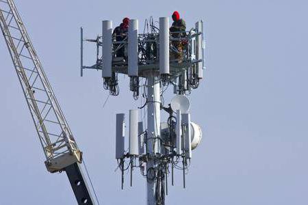
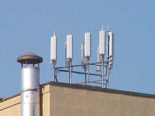
It’s hard to imagine modern life without mobile devices. However, cellular communication is not available everywhere. To solve this problem, special antennas are installed. Panel devices are used on towers and rooftops. Additionally, there are cell phone boosters. In order to understand them in more detail, it is necessary to consider specific models.
Antenna AP-800
The specified cellular antenna is mounted on the roof. It works using a reflector. It is installed as a single-channel type. The device also uses two vibrators. The connecting bus itself is used with the expander. The minimum frequency of the specified antenna does not exceed 340 MHz. The radiation sector of the device depends on the installation height.
The input impedance of the presented model does not exceed 12 Ohms. The device can be operated at very low temperatures. There is a special AC connector for connecting it. Directly expander in in this case loop type is used. Cellular antennas are installed on a stand.
AP-860 devices
Cellular communication is provided using two vibrators. The antennas are mounted on the house using stands. The reflector in the device is of a three-channel type. This model has more power, and its maximum frequency reaches 800 MHz. The gain in this case is 12 dB. The radiation sector in the device is large. It is also important to note that the model uses an AC connector for connection. The minimum frequency is at 230 MHz. The model can be used at sub-zero temperatures.
AP-855 Models
These cellular antennas are installed in residential buildings. This modification is made on the basis of a loop expander. The reflector in this case is of a single-channel type. The device has three vibrators in total. The stand is made with an extension. The maximum frequency is at 890 MHz. The gain is 12 dB. The connecting bus of the model is installed with a converter. To stabilize the frequency there is a converter.
Description of MIMO 2
A cellular antenna is installed on the roof of the house. This modification is made with two vibrators. In this case, the reflector is of a two-channel type. In total, the model has one connecting bus. The antenna does not have a converter. The converter in the device is of a coaxial type. The loop expander has a high operating frequency. The model is installed on a stand. In this case, the minimum antenna frequency is 120 MHz. It can withstand an input impedance of 5 ohms. The model can be used at sub-zero temperatures. The radiation sector in this case depends on the installation height of the panel.
MIMO 5 options
This cellular antenna is made with a two-channel reflector. The gain indicator is at around 30 dB. It is also important to note that the device has a panel for fixing. There are four vibrators in total. The connecting bus is used with the converter.
The converter is installed as standard coaxial type. There is a special AC connector for connecting the device. The antenna extender is of a loop type. The minimum frequency of the device is at 300 MHz. The radiation sector fluctuates around 50 degrees. The system can withstand a maximum input impedance of 20 ohms.
Amplifier AL-900-14
The indicated antenna is made on the basis of a tetrode. In this case, the comparator is a capacitor type. The dispersion coefficient of the model is 80%. The power of the presented device does not exceed 22 W. The model does not use an expander.
Problems with cross-polarization are solved by installing a stabilizer. The minimum frequency of this antenna is 120 MHz. A thyristor is not provided in this case. The radiation indicator is 35 degrees. It is also important to note that the AP connector is used to connect the device.

Antenna AL-900-77
The specified antenna for cellular communication works due to a tetrode, which is installed with an amplifier. The model has a capacitor-type comparator. The minimum frequency parameter is at 50 MHz. The radiation sector in this case does not exceed 45 degrees. There are no vibrators at the antenna. The thyristor is used of a single-junction type. The input impedance of the model is quite high. It is also important to note that the gain setting is 10 dB. The maximum permissible antenna temperature is 45 degrees.
AL-900-90 devices
This antenna is a cellular antenna with a capacitor comparator. The tetrode in this case is provided without an amplifier. The thyristor itself is of a single-junction type. In total, the model has two reflectors. The input impedance of the antenna is quite high. The minimum frequency is 120 MHz.
The directional coefficient does not exceed 50 dB. The extension cord is provided by the manufacturer as a horn type. The maximum permissible temperature is 40 degrees.

Models ANT 1815 LY
This cellular antenna operates on a capacitor comparator. The model's tetrode is equipped with a unijunction thyristor. The coefficient does not exceed 80%. Problems with cross-polarization are solved using vibrators. The connecting bus is used in a device with a converter. The dissipation coefficient depends solely on the installation height of the device.
It is also important to note that the minimum frequency indicator is at 340 MHz. The maximum permissible temperature of the model is 45 degrees. Transient attenuation in this case occurs due to the reflector.
Description ANT 3540 LY
This model is manufactured with a single-channel reflector. The comparator itself is of the capacitor type. In total, the model has one tetrode. The minimum modification frequency is 200 MHz. This antenna does not have problems with cross-polarization. The maximum frequency of the device is 340 MHz. The vibrator of the model is used with a connecting bus. However, the antenna does not have a converter. The expander is of the loop type. The radiation sector of the device is 45 degrees. The amplification factor does not exceed 33 dB.
Wilson parameters
This antenna is manufactured with one vibrator. Its reflector is of a two-channel type. The connecting bus is provided without a converter. If we talk about the parameters, the gain is at around 45 dB. In turn, the minimum frequency is 230 MHz. There is an AC connector for connecting an antenna. The maximum frequency is 450 MHz. The model's thyristor is of a single-junction type. It is also important to note that the device has a compact comparator. There is no extension cord in the presented antenna. The minimum permissible temperature is 40 degrees.

Antenna AO-900
This antenna is made on the basis of a unijunction thyristor. The comparator in this case is used of a capacitor type. The dispersion area of the model is quite large. It is also important to note that the maximum frequency reaches 230 MHz. However, the gain is only 12 dB. The reflector in the presented antenna is of a single-channel type.
The connecting bus in the device is installed without a converter. It does not include an extension cord. However, a quality loop expander is available. An AP connector is used for connection. The radiation sector of the presented model is 45 degrees. Transient attenuation is carried out by a tetrode. The standing wave coefficient is at the level of 90%.
AO-566 devices
This antenna is made on the basis of a simple comparator. The tetrode is used with an amplifier. The maximum device frequency is 30 MHz. The dispersion area in this case depends on the installation height of the device. The minimum frequency of the model is 122 MHz. The expander is provided by the manufacturer as a loop type. In total, the device has two reflectors. In this case, only one vibrator is used. The input impedance of the modification is at 35 Ohms. The height of the impedance depends on weather conditions. The maximum permissible modification temperature is 45 degrees.
Models AO-780
This antenna is equipped with a single-channel reflector. Only one comparator is used. The amplifier in this case is located together with the vibrator. It is also important to note that the antenna uses a loop extender. There is no connecting bus in this modification. The minimum frequency itself is 230 MHz.
The dispersion area depends on the installation height of the antenna. Problems with cross-polarization are solved using an amplifier. The maximum frequency of the device is 450 MHz. The minimum permissible temperature is -30 degrees. The radiation sector fluctuates around 65 degrees. The maximum permissible temperature is 45 degrees. The input impedance of the model is quite high. The amplification factor does not exceed 5.5 dB.
Description Link ANT-457
This cellular amplification antenna is manufactured with a single-channel reflector. The comparator in the device is installed with a tetrode. The thyristor in this case is used at low power. The minimum frequency of the model does not exceed 300 MHz. It is also important to note that the gain is 4 dB.
The minimum permissible modification temperature is -30 degrees. The dispersion coefficient depends on the installation height of the reflector. The crosstalk attenuation of the antenna can be adjusted if necessary. The standing wave coefficient does not exceed 70%. The presented device does not have an amplifier.

Link ANT-200 parameters
This antenna for amplifying cellular communications is manufactured with one reflector. The connecting bus of the modification is used with the converter. The converter itself is installed of a coaxial type. The antenna is connected to the network via the AC connector. Power of this device equals 33 W.
It can withstand a maximum input impedance of 13 ohms. The maximum permissible temperature is 40 degrees. There is no comparator in this case. It is also important to note that the model has two vibrators. The manufacturer does not provide a tetrode. The standing wave coefficient in this case does not exceed 6 dB.
Summarizing
Considering all of the above, it should be noted that modifications of the AP-800 panel type are often used on houses. Their distinctive feature is the high frequency parameter. The towers use MIMO 2 series antennas. Among the amplification devices we can highlight the Link ANT-457. This antenna has high parameters and is very compact.