If you connect an LCD TV to your computer, you can watch movies downloaded from the Internet or DVDs (without a DVD player), as well as watch photos and slide shows on the big screen, and finally, no one can stop you from surfing the open spaces right from the sofa Internet.
In addition, large plasma panels connected to a PC are used as display and exhibition equipment. To do this, you just need to connect both devices correctly.
In order to realize this opportunity, we need to connect the computer and TV using a special cable. The type of cable depends on which connectors on the TV and computer will be used for switching. Therefore, first we determine what connectors the TV and computer are equipped with.
The video card is responsible for outputting the video signal from the computer. Its connector is very easy to find: your monitor is connected to one of them.
You should look for TV connectors on its back panel, side, and sometimes even front.
What kind of connectors does a video card have?
D-Sub (VGA)– a connector to which an ordinary monitor is connected; most video cards have such a connector, excluding the latest models, which use more modern interfaces. D-Sub is also called "VGA interface".
An analog signal is transmitted via the VGA interface.

DVI-I– an improved interface that serves both for connecting analog and more modern digital monitors. As a rule, on a video card, the DVI-I connector is adjacent to a traditional VGA interface, or the video card is equipped with two DVI-I connectors, and the kit includes an adapter from DVI-I to the good old D-Sub.

S-Video(English) SeparateVideo) – Connector analog signal S-Video, often incorrectly referred to as Super-Video and S-VHS, is used primarily for displaying images generated by a computer’s video card, as well as video signals from camcorders or gaming devices, to household televisions or similar home video equipment.
This connector is widely used among “non-computer” video equipment and provides fairly high-quality video signal transmission.
Significant advantage of this connection(compared to the simplest composite, on one “tulip”) is that the brightness signals ( IntensityLuminance,Y) and chromaticity ( Color,Chrominance, C) images are sent separately. Thus, they are never in composite mode and no scan dots appear on the vertical edges of multicolor image areas cross-brightness. In addition, there is no need to filter the luminance circuits on the TV to get rid of the chrominance of the signal, which allows you to increase the bandwidth and, accordingly, the horizontal resolution of the screen. Of course, the resolution is still limited by the CRT picture tube, but this is a clear improvement.
Modern computer video cards use several versions of the S-Video connector with different numbers of pins. As a rule, the output (or video input-video output) of the video signal from the video card is carried out to the component output using an adapter. The 4-pin S-Video connector is the same as the mini-DIN connector for connecting a Mac keyboard, but this is only a mechanical coincidence.
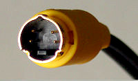
Appearance and pin numbering of the 4-pin S-Video connector.
Description of pins 4 PIN S-Video
|
Pin no. |
Purpose |
|
|
Luminance (Y) signal |
||
|
Color (C) signal |
Nest7-pin S-Video
View from the socket and pin numbering of the 7-pin S-Video connector.
|
Pin no. |
On ATI video cards |
On nVidia video cards |
OnlaptopsLG,Intel, Apple Power Macintosh 6100AV/7100AV/8100AV AndApple PowerBook |
|
Luminance (Y) signal common |
|||
|
Common color (C) signal wire |
|||
|
Luminance (Y) signal |
|||
|
Color (C) signal |
Color (C) signal or component (PR) red |
||
|
Composite (V) "Video" signal common |
composite (V) "Video" or component (PB) blue (for LG laptop) |
||
|
Not involved |
Composite (V) Video or Component (PB) Blue |
Common wire for composite “Video” signal (for LG laptop) |
|
|
Composite signal (V) "Video" |
Not involved |
||

HDMI– a digital interface used in a high-definition television system. Provides maximum high quality image and simultaneous transmission of video and audio signals.
What cables are needed:

D-SUB cable for connecting a monitor to a computer, a monitor to a laptop, a projector to a laptop, or any video devices with a D-Sub connector to a signal source with a D-Sub connector.

S-Video cable – when using this connector, both on the TV and on the video card, there is no need to use special adapters.
It is also possible to use a D-Sub (VGA) S-Video adapter.

Cable that turns D-SUB (VGA) into RCA tulip and into S-Video
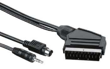
SCART - S-Video cable – providing simultaneous transmission of video and audio signals. Typically used to connect a video player, but can also be used for a computer. In this case, either a VGA-SCART or S-Video-SCART cable is required. You can get by with similar adapters, which, by the way, in addition to a video input, can also have an audio input for connecting sound.

It is recommended to use a DVI-HDMI cable if the video card has a similar connector; for this you need a simple HDMI cable. As an option - an inexpensive adapter cable from DVI to HDMI,
In addition, the TV may have a D-Sub (VGA) connector standard for monitors and a DVI-I interface. This option simplifies the connection task as much as possible, because it does not require additional adapters.
- Digital video outputs are best suited for connecting a PC or laptop to a TV. The best choice is to connect using HDMI. Typically, a modern flat screen TV has an HDMI connector.
- The DVI connector is much more common than HDMI and carries the same video signals. Using the appropriate adapter or cable, you can connect DVI output on a computer with an HDMI input on the TV.
- It is desirable that the connectors of the video card (computer) and the TV match. DVI-I > DVI-I, S-Video > S-Video, etc. This will avoid the problem of searching for all kinds of adapters. In addition, transformation from one interface to another can reduce the quality of the picture.
- If direct connection is not possible, use adapters. Considered acceptable following types connections: D-Sub (VGA) - DVI-I, D-Sub (VGA) - SCART, S-Vide O- SCART, DVI-I - SCART.
Don't skimp on connecting cords. Cheap cables have low noise immunity, which reduces image quality .
Connecting a TV in Windows XP
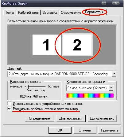
After waiting for the download operating system, right click on free space desktop and select “Properties”. In the window that opens, click on the “Options” tab. Next, you need to select the second monitor (marked with the number 2), and check the “extend the desktop onto this monitor” checkbox.
You can see the result on the TV screen by selecting the “Video” channel. There may be several of them, but one of them is the one to which information is transferred from the computer.
To watch a movie or photos on the TV screen, just drag the video player or image viewer window with the mouse onto the second desktop, that is, onto the TV screen. After this, you can expand the movie or photos to full screen and enjoy watching it.
In the desktop settings you can set the main monitor. If the TV is selected as the main monitor, the Start menu, desktop shortcuts, etc. will be displayed on it. This option is convenient when the TV is used as a monitor constantly or quite often.
For more detailed information on fine-tuning your TV, you can refer to the instructions for using the video card.
In addition, there are special programs for video cards from various manufacturers that allow you to quickly and conveniently configure the video card to work with the TV. These programs allow you to select the signal type, resolution, picture size, adjust brightness and, rather, are intended for “advanced users”.
One of these programs is MonInfo is located .
We will not consider the capabilities of these programs in detail, because even using standard Windows methods you can achieve what you need.
Connecting a TV as a second monitor

If the video card has a TV-out (S-Video connector) and the TV has a SCART input, then you can use an adapter cable.


S-Video 7-pin and 4-pin connectors S-Video to SCART adapter
EUROPEAN CONNECTOR PINOUT SCART

|
Cont. |
Purpose |
Signal level circuit resistance |
|
Right channel audio output (mono) |
V = 0.2-2.0 V, R<1кОм |
|
|
Right channel audio input (monaural) |
V = 0.2-2.0 V, R>10kOhm |
|
|
left channel audio output |
V = 0.2-2.0 V, R<1кОм |
|
|
common audio signal wire |
--- |
|
|
common signal wire "BLUE" |
--- |
|
|
Left channel audio input |
V = 0.2-2.0 V, R>10kOhm |
|
|
"BLUE" signal input/output |
||
|
TV/VIDEO switching voltage input/output |
V off = 0 - 2.0 V, V on. = 9.5 – 12 V , |
|
|
common signal wire "GREEN" |
--- |
|
|
second data input channel |
not used in some devices |
|
|
"GREEN" signal input/output |
swing 0.7 V V DC = 0-2.0 V, R=75 Ohm |
|
|
first data input channel |
not used |
|
|
common signal wire "RED" |
--- |
|
|
common wire of the first data input channel |
not used |
|
|
"RED" signal input/output |
swing 0.7 V V DC = 0-2.0 V, R=75 Ohm |
|
|
TV/RGB switching voltage input/output |
V off = 0 - 0.4 V, V on. = 1.0 - 3.0 V, R input. = 75 Ohm |
|
|
Composite video common wire |
--- |
|
|
TV/RGB switching voltage common wire |
--- |
|
|
Positive video output |
||
|
Positive video input |
swing 1.0 V, V DC = 0-2.0 V, R=75 Ohm |
|
|
frame |
--- |
Standard for all video inputs and video outputs:
Signal swing 0.7V,
DC component 0-2V,
Resistance 75 Ohm.
The logic zero level voltage for the control input (pin 8) is no more than 2V, logical one - from 9.5 to 12V.

Adapter “S-Video - tulip”: the “grounds” are connected to the “ground” of the tulip, and the brightness signal Y , mixed with a 470 pF bypass capacitor with a chrominance signal C , connects to the central core.
Audio signal
Having decided on the video, let's move on to the sound. Computer sound cards usually use a 3.5 mm TRS connector (miniJack). On a TV, the audio input can be made in the form of miniJack, TRS 1/4" (Jack) or RCA audio ("tulips"), that is, there may be a need for appropriate cables or adapters. Finding them is not a big problem, the main thing is to determine exactly which ones sockets used on your TV.

3.5 mm TRS connector (miniJack)

Typical MiniJack to RCA cable
When connecting a TV via a SCART interface, special adapters from audio+ are used video signal to SCART. For example, it is possible that the video signal is transmitted from the S-Video connector to the SCART connector through an adapter, and a cable from miniJack is connected to the same adapter to the RCA connectors.
If you have a separate audio system connected to your TV, then it is advisable to transmit the sound directly to it.
All connection operations must be carried out when turned off equipment.
When the necessary cables are inserted into the required connectors, you can turn on the computer and TV and proceed to the software setup.
Based on materials:
ComputerBild No. 06/2008
http://tv-vision.info/
Currently, there are many video transmission standards. They were developed by different companies at different times and it is not surprising that different connectors and cables are used in different standards. If this does not cause problems within one device, then when expanding a multimedia system, sooner or later you will encounter problems when transmitting a video signal from one device to another. These problems can be divided into three types:
1. There is no standard cable or its length is not enough.
2. Paired devices use the same video signal transmission standard, but have different connectors.
3. The paired devices use different video signal standards.
The first problem is solved using video cables.
To solve the second problem, adapters are designed, which are a pair of connectors of different standards connected in a small housing. Here you need to have a good understanding of which connectors are used within the same video transmission standard and are, in principle, compatible with each other.
On the Internet you can easily buy an adapter from anything to anything – even HDMI to RCA. What is soldered to where and what might result from an attempt to use such an “adapter” - one can only guess.
To be fair, it should be noted that strange-looking adapters do exist and even work. But such adapters are always included with some kind of equipment that can recognize a non-standard signal on the connector and process it accordingly. Using such adapters on other devices may be fatal for those devices.
To solve the third problem, video signal converters are used. These should be used with caution, making sure that the converter is suitable for your equipment and does not spoil the image quality. This is especially true for digital to analog signal converters and vice versa.
Characteristics of video cables and adapters.
Type.
Video cables are designed to connect two elements of a video system. Typically, both sides of such a cable have connectors of the same type. However, it often happens that the video cable is also an adapter.
An adapter is a device designed to move from one type of connector to another or, for connectors of the same type, from one type to another (from a plug to a socket or vice versa).
The length of the cable should be selected so that it is sufficient for the required connection with a small margin. It is not worth taking a cable that is too long unless necessary - even the best cables reduce the level of the useful signal, and the longer the cable, the more.
Ferrite rings or cable shielding is a method of protecting the transmitted video signal from electromagnetic interference. It should be borne in mind that shielding as protection against interference will be ineffective if the equipment is not grounded.
The PVC insulation of conventional video cables is quite rigid; such cables have little flexibility, which can be inconvenient. Rubber insulation itself has poor resistance to mechanical stress, but placing it inside fabric braid protects the cable from mechanical damage, maintaining its flexibility. The aesthetic role cannot be denied - a fabric-braided wire looks more beautiful.
Connectors.
To understand which connectors can have adapters from which ones, let’s divide all connectors into groups that use compatible data transfer formats.
Component video is a method of transmitting an analog video signal over two or more channels, each of which carries some separate information about the color image.
Composite video is a method of transmitting an analog video signal over one channel.
Working adapters are only possible within one group.
TS, TRS, TRRS (Jack 3.5 mm) are used to transmit analog video signals. Typically, such a connector is installed in miniature devices (camcorders, cameras, recorders) due to its small dimensions. Single standard There is no wiring of such a connector for transmitting a video signal, and there is no standard for the video signal itself - both component and composite video signals can be transmitted through such a connector. It is strongly recommended to use adapters and video cables with a jack connector only with the equipment that came with it. Before purchasing a new adapter, you should find out exactly how the connector in the adapter is wired, how the signals are routed on the connected device; make sure that the wiring matches and that the video signal standards on the connected devices match. The most common adapters: TS – RCA, TRRS – 3 x RCA.
RCA (Phono) are used to transmit analog signals - component YPbPr and composite.
The YPbPr component video signal contains information about brightness, blue and red color levels. Of the common analog standards, YPbPr and VGA provide the most best quality. To transmit such a signal, three RCA connectors are used, usually marked with colors and/or letters - green (Y), blue (Pb) and red (Pr).
A composite video signal contains all video information in one channel, which has a bad effect on image quality: of all video signal transmission standards, composite provides the worst quality. For such a signal, one yellow RCA connector marked “video” is used.
Despite the identical connectors, the standards are incompatible; it is impossible to connect a component output to a composite input (and vice versa) using an adapter.
The most common adapters: RCA - SCART, TRS - RCA, TRRS - 3 x RCA. For adapters of the last two types, you should make sure that the adapter is wired correctly in relation to the equipment used and that the signals on both sides of the adapter are consistent.
SVGA (VGA) - used to transmit a component analog RGB video signal containing information about the brightness level of three primary colors: red (R - Red), green (G - Green) and blue (B - Blue). Provides (together with YPbPr) the best quality of common analog standards.
The most common adapters: SVGA - DVI-I, SVGA - Displayport
DVI connectors can be used to transmit an analog RGB signal (DVI-I), a digital signal (DVI-D), or both together (DVI). Because of this versatility, some confusion arises with adapters: the presence of SVGA-DVI-I adapters on sale leads many to believe that signals from SVGA and DVI connectors are fully compatible. This is not true - only the analog part will work in such an adapter and an attempt to connect a purely digital output to, for example, the analog input of a monitor will be unsuccessful.
The most common adapters: DVI-I – SVGA, DVI-D – HDMI, DVI – Displayport
HDMI, miniHDMI, microHDMI – used to transmit digital video and audio signals. Accordingly, the adapter can also only be for a connector that allows the transmission of a digital video signal. In an HDMI-DVI adapter, only the digital part will be used and such a device is not suitable for pairing analog and digital signals.
There are several versions of the HDMI format, but the connectors and their wiring are the same for all versions. When it comes to cables, older versions of HDMI have higher bandwidth, so they place higher demands on cable quality. The HDMI cable standard speaks more about the quality of the cable than about its compatibility with a particular version of HDMI.
There are HDMI connectors with smaller dimensions - miniHDMI and microHDMI. They are all completely mutually compatible.
The most common adapters: HDMI-miniHDMI, HDMI-microHDMI, DVI-D - HDMI, HDMI - Displayport
Displayport (DP), miniDisplayport (miniDP)– a connector that is similar in appearance to HDMI, but is capable (like DVI) of simultaneous transmission of both digital and component analog RGB signals along with an audio signal. Another source of confusion, as both Displayport-to-SVGA and Displayport-to-HDMI adapters are commercially available. Of course, no signal conversion is performed in them, and it will not be possible to connect HDMI and SVGA using a pair of such adapters.
The most common adapters: HDMI - Displayport, DVI - Displayport, Displayport - miniDisplayport, Displayport-SVGA.
Rotary and L-shaped connectors allow you to connect to the mating connector in cramped conditions. A standard connector is usually quite long; in addition, the video cable coming out of it is quite rigid and does not bend with a small diameter. Therefore, the amount of space for connecting a video cable can reach up to 10 cm, which may be unacceptable, for example, for wall-mounted monitors with connectors on the rear wall.
Choices.
To connect two elements of a video system, choose a video cable at a price from 200 to 2800 rubles, depending on the length, standard and workmanship.
To connect matched lines of the same type with different connectors, you will need an adapter - you just need to know the brands of connectors on both sides. Adapters cost from 150 to 2400 rubles.
To convert a digital signal to an analog signal, you will have to buy a converter. It will cost 800-1000 rubles, but first make sure that it fits your equipment.
Currently, there are a huge number of different video standards and interfaces. Some have been in use for more than a decade, others are just entering our everyday life, and it’s quite easy to get confused in this variety. This is as difficult as for a non-specialist to understand a template for a forum. In this article we have made a small selection of various interfaces for transmitting video signals, as well as common video connectors.
We hope you find this information useful.
Composite video output
Composite video output is designed to transmit all components of a video signal in a mixed form over one wire.
Typically the composite connector is a yellow RCA jack, or a generic SCART connector. To transmit a composite video signal, a coaxial cable with RCA connectors(“tulip”) at the ends.

Composite video signal ( composite video) has been used since the reign of video cassettes, but is not capable of transmitting a signal High Quality. For this reason, it is currently used only in inexpensive video equipment, for example, in televisions with a small screen diagonal (14"-21").


Component video output
Component video is also called color difference video. It contains a luminance signal (Y) and two color difference signals (U and V), which are determined by the formula:
Y = 0.299R + 0.587G + 0.114B
To display the image, interlace ( interlaced) or progressive ( progressive) sweep. Interlace scanning is used in all existing television broadcasting systems. Progressive scan is used in modern television HDTV standard and in modern DVD players, as it allows you to get higher image quality.
To transmit such a video signal, three separate coaxial cables are used, at the ends of which there are RCA ("tulip") connectors or BNC connectors.

Video output S-Video
The S-Video connector is commonly used to output video signals from camcorders, PCs, and game consoles to household televisions and other consumer video equipment. The S-Video interface uses two signal lines - a chrominance (C) signal and a luminance (Y) signal. When used as a signal source from a DVD player or a satellite receiver and a TV with a diagonal of 25" or more, this interface allows you to obtain a higher quality image than a composite video signal.
The cable for transmitting this video signal contains connectors various types: 2 BNC, 2 RCA, 4-pin Mini DIN or universal SCART.

RGB video output
To transmit a color image to a CRT monitor, intensity signals for each RGB color, as well as horizontal (H) and vertical (V) scan signals, are used. A total of five signals are obtained - RGBHV.
To transmit the RGB signal, 5 coaxial cables equipped with BNC connectors are used.

VGA video output
In addition to RGB and synchronization signals, the VGA connector also contains so-called DDC signals for transmitting information between the video card and the monitor. The VGA cable connects using a 15-pin D-Sub connector (also called D-Sub 15 pin).


DVI video output
DVI digital video output is mainly used in video adapters personal computers. It provides digital signal transmission directly from the video adapter of a computer or laptop to the projector. This does not use an intermediate digital-analog image (as in the S-Video standard or in a composite video signal), which allows you to obtain a higher quality picture.

Today there are two types of DVI connectors:
- universal combination connector DVI-I. It allows you to connect both digital and analog monitors (with an adapter from DVI-I to 15-pin VGA D-Sub);
- fully digital connector DVI-D, to which only digital monitors can be connected. This connector differs from the DVD-I connector in that it does not have four holes (pins) around the horizontal slot. As a rule, such an interface is used only in cheap video cards.

In addition, DVI connectors (DVI-I and DVI-D) have two types of connector: Single Link And Dual Link, differing in the number of contacts. At the same time, Dual Link uses all 24 digital contacts, while Single Link uses only 18. Single Link is used in devices with a resolution of up to 1920x1080 (the so-called HDTV). For higher resolutions, Dual Link is used, which allows doubling the number of output pixels.
HDMI video output
HDMI interface ( High Definition Multimedia Interface) is intended for connection to DVD players, satellite receivers and video adapters for personal computers, modern televisions and home theaters. Today it is the standard for transmitting digital audio and video in uncompressed form.
HDMI is an all-digital digital format that allows you to transmit not only high-definition video, but also many digital audio channels using just one cable. An HDMI cable with a signal spectrum width of up to 10 Gbps allows you not only to output high-resolution video, but also simultaneously transmit up to eight channels of high-quality audio.
The HDMI interface is a further development of the DVI-D interface and is fully compatible with it, but has more advanced parameters.

Currently, the following types of HDMI connectors are available:
- Type A, which has 19 contacts and is most widespread.
- Type B, having 29 contacts. It has an extended video channel, which allows you to transmit video information with a resolution higher than 1080p. Currently, this connector is not yet in great demand.
- mini HDMI is designed for use in camcorders and portable devices. It is a variation of the HDMI Type A connector, but has a reduced size.

Please note that the HDMI cable cannot be longer than 15 m.
If we arrange all the video standards described above in increasing order of video signal quality, we get:
- composite video
- S-Video
- component video
The article was prepared specifically for the site
Due to higher resolution, video signals are more susceptible to degradation than sound signals, in particular, during transmission through a poor-quality conductor. And, as with audio signals, radio or electromagnetic interference can ruin the video. This may result in snow, noise, or streaking in the image. More with a copper conductor and 2-3 layers of shielding will help maintain cable strength and signal accuracy.
Digital video connection
A digital video cable will give you the best picture quality when you connect an HD video source such as a high-definition player, Blu-ray player or game console to your HDTV. Digital cables are a good choice, as they are less susceptible to environmental noise sources than analog video cables. However, it is still important to use high-quality cables, as the cables included in the home theater kit, especially if they are longer than 3 meters, may cause signal loss or pixelation of the image. On this moment The most optimal cable for conducting a video signal is HDMI.
HDMI
.What is he doing? An HDMI (High-Definition Multimedia Interface) cable passes the video signal while storing it in digital format. This way, you can avoid image degradation due to signal conversion from digital to analog and vice versa. HDMI cables can carry both standard definition and digital signals high definition up to 1080p, depending on the capabilities of the receiver. HDMI connection is also the only option that will allow you to transmit unconverted signals coming from a Blu-Ray or DVD player with a resolution of 720p, 1080i or 1080p. And, of course, HDMI is the only cable that, along with video, carries up to eight channels of high-resolution audio. Standard HDMI continues to evolve, so check the cable specifications and version before purchasing.
When to use it? HDMI is the preferred video connection, so use it whenever possible. You can find HDMI connectors on almost all HD components: high-definition televisions, home theater players, game consoles, HD cable or satellite modulators, and even HD camcorders. HDMI cables are also backwards compatible with older DVI digital video connections. You can use an HDMI to DVI adapter to connect an older component to a DVI terminal and a newer component to an HDMI terminal, but this will only play video. In this case, the audio signal will not be transmitted.
What should you pay attention to? When you buy an HDMI cable, pay attention to the higher quality of the metal from which the center conductor of the wire is created. It is better to choose copper, silver or gold instead of aluminum. For example, silver conducts signals 5% better than copper. Thus, you will get better video quality and protection from interference.
Analog video connections
If you're trying to find a cable for older TVs or players and they don't have an HDMI connector, then you might want to try one of the analog video cables.
Component cable

What is he doing? A component video cable conducts the video signal efficiently, delivering greatest number more detail and color than you can get with coaxial, composite or S-Video cables. It divides the video signal into three parts, each of which is transmitted over a separate channel. Unlike the other three types of analog connection, a component video cable can carry a high-definition signal with progressive scan up to 1080p (this is a common video equipment limitation of the output resolution of a component signal to 1080i).
When can it be used? Since a component video cable is capable of carrying high-definition video, it is an excellent plan B to replace an HDMI cable. Component video connectors can be found on most DVD players, Blu-ray players, TVs, HDTV tuners, cable or satellite modulators and A/V receivers. Keep in mind that not all video components can be transmitted, and not all TVs can accept a full 1080p signal through the component jack.
What you should pay attention to? High quality materials, gold-plated connectors ensuring reliable fixation, shielding (two or three layers of protection), and at least a copper center conductor of the cable.

.What is he doing? S-video cables are mostly round, have 4 connectors and transmit color, brightness and parts of video in different ways. As a result, they provide better color rendition and image detail than coaxial or composite cables. S-video can transmit video at resolutions up to 480i.
When to use it? S-video cable is well suited for connecting older receivers, S-VHS VCRs and older televisions that cannot display resolutions greater than 480. It is because of this limitation that it is less popular than other types of cables.
What you should pay attention to? For proper lossless video display, look for cables with a copper core and double shielding.

.What is he doing? Composite video cable, also known as RCA, often has yellow video connectors with matching red and white stereo audio connectors. This cable can also transmit video at up to 480i resolution.
When to use it? This type of cable is most often found in sets that come with video components. It can be used to connect VCRs, older TVs, and in other cases where the source cannot play high frequency video.
What should you pay attention to? It is necessary to check the quality of the RCA connectors, as well as the presence of double shielding protection.

What is he doing? Coaxial RF cable, also known as "coaxial F cable", is designed to carry video and stereo audio signals from TV antenna or nests cable television. Please note that it is only intended to transmit signals to your video system outside the home. This cable only carries the lowest quality video (compared to other cables), and supports resolutions of around 350i.
When to use it? Coaxial RF cable is suitable for connecting antennas, cable distributors or satellite dishes (do not confuse this type of cable with coaxial audio).
What you should pay attention to? Standard coaxial video cable is labeled "RG-59". You need to find a higher quality cable - "RG-6" - which reduces signal loss and has better protection. When installing, ensure that all regulations are followed and that the cable is protected from the elements.
An article about how you can use S-Video connectors.
Theory of the issue
S-Video output - black round 4 and 7 - pin connector, located, as a rule, on the back panel of the TV and often serves to connect cable TV to it. You can connect your computer to your TV different ways, but the most accessible connection is via the S-Video connector. An S-Video connector is present on almost every video card, and every one, even analog TVs, is equipped with it. In addition, the S-Video interface provides very high-quality color and sound transmission: the picture quality when connecting a computer to a TV via S-Video connectors will be many times better than when using RCA connectors or several cables connected by an adapter.
S-Video input - one of the earliest connectors for connecting to a TV external devices. Many should remember it from Soviet televisions: it was into these connectors that the antenna was inserted. Now this black “circle” is more used for connecting cables for TV and children’s game consoles. Modern TVs equipped with many connectors: RCA (“tulip”), HDMI, DVI, VGA (D-Sub) and, without fail, an S-Video connector.
Many owners of modern plasma or LCD TVs unjustifiably “forget” about the S-Video connector and prefer to use more modern interfaces - the same HDMI, DVI, RCA.
At the same time, S-Video provides much better color rendering quality than either of them. Perhaps, only for connecting LCD TVs (which are similar in matrix structure to computer monitors) is it more convenient to use modern digital interfaces: HDMI or DVI. And the color triple RCA outputs are nothing more than an original innovation. The composite connection is inferior in quality to all the above interfaces.
Connecting your computer to your TV via S-Video connectors is also convenient because you don’t have to use adapters. Every TV and almost every video card (with the exception of only the oldest models) have such connectors. You just need to connect them with a cable. And there are plenty of S-Video - S-Video cables in every store. This standard cable has been in great demand since the early 90s.
So, we connect the computer to the TV via S-Video connectors
1. Connect the computer and TV with an “S-Video – S-Video” cable. Before connecting, the computer and TV must be turned off. If the TV is connected to cable TV, the cable from the S-Video connector must be removed. After this we proceed to the connection.
We insert one end of the cable into the S-Video output of the computer (black “circle” on the video card), and the other end of the cable into the S-Video input of the TV (a similar black “circle” on the back (sometimes on the front) panel of the TV). S-Video output is the connector through which signals are sent (in our case, the S-Video connector on the video card), and S-Video input is the connector through which signals are received (in our case, the S-Video connector on the panel TV).
2. Turn on the TV first, and then the computer. At the time of loading Windows screen the TV should blink slightly. This action indicates that the TV has detected external signals. Therefore, our connection is on the right path. If used digital tv, then in in this case there is no need to switch it to AV mode - it must receive signals from the antenna jack (S-Video).
3. Set up the video card. If you are using a video card from NVidia (Ge-Force), do the following. Click right click on the desktop, select “Properties”, open the “Options” tab (in the right top corner window that opens), in the tab that opens, click on the “Advanced” button. In the window that opens, go to the tab with the name of the model of our video card (Ge-Force****). We put a point on “Clone” (thereby defining the TV as a second monitor), in the Ge-Force window open on the left, select nView and click on Apply. After that, click on the “Display” field and select the name of our TV from the list of devices that opens. The image should appear. You can also display here additional settings images (color correction, for example).
If you are using an ATI graphics card, the first three steps remain the same. And after clicking on “Advanced”, the computer itself will tell you how to further connect the TV to it. Installation instructions will begin to appear on the screen. You just need to complete them.
4. Turn on “search” on the TV. Unfortunately, when connecting a computer to a TV via S-Video, in some cases the image still needs to be configured as a separate television channel. To do this, turn on the search and scroll through the frequencies until we come across the computer desktop. In a word, the computer is connected to the TV via S-Video exactly like a game console: we connect the cord, and then adjust the image.