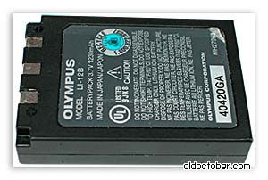
The battery voltage was about 3.1 Volts, which is less than the threshold at which some chargers recognize the battery and begin charging it. At least that's what happened with my Blackberry battery, which was too deeply drained.

The LI-12B battery was brought back to life by charging it with a small current, about 100 mA. For this purpose it was collected simple circuit. When the battery voltage reached 4.2 Volts, I stopped the charge and checked the camera's functionality. The camera started working and I began to think about how to repair the charger. https://site/
Repair of charger LI-10C.

This is what it looked like when I got it Charger.

To disassemble the LI-10C charger, it was necessary to unscrew two self-tapping screws, one of which was located under the sticker.
Checking the operation of the charger revealed the presence of short-circuited turns in the isolation transformer pulse block nutrition.

The pulse transformer turned out to be beyond repair, and besides, I did not have a suitable ferrite core to be able to wind a new transformer.
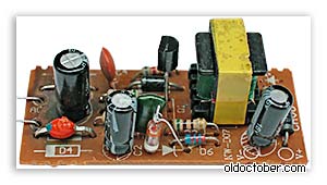
The picture shows the charger circuit board. The arrow marks the transformer DS-4207 KT04044.
I decided to go to our radio market after the weekend, but then I remembered that I have a five-volt charging board for mobile phone.

I once bought this charger in a faulty condition for the sake of a plug-in case so that it could accommodate a power supply for a radiotelephone, which was once designed for a mains voltage of 120 Volts.
To check the transformer, I first had to draw a diagram and then replace all the burnt parts.
To my joy, the transformer turned out to be good, and in terms of dimensions, it seemed to be just right.
Actually, all further repairs consisted of replacing the transformer.
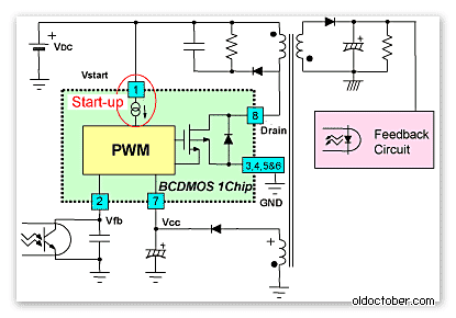
If you look at a typical circuit diagram for connecting the PWM driver microcircuit of this FSDH0165 charger, you will notice that the transformer from the diagram above is functionally not much different from the burnt one.
As a rule, repairing such an inexpensive device is not economically profitable.
Especially in non-poor countries. Average price 5 dollars.
But it happens that there is no extra money, but there is time and spare parts.
There is no store nearby. Circumstances do not allow. Then it's not about price.
In my case, everything was simple - one of my two chargers broke Nokia AC-3E, friends brought a bag of broken chargers. Among them were a dozen branded Nokia chargers. It was a sin not to take it.
The search for the circuit did not lead to anything, so I took a similar one and converted it to the AC-3E. Many chargers for mobile phones are made using a similar scheme. As a rule, the difference is insignificant. Sometimes the denominations are changed, a little more or a little less elements, sometimes a charge indication is added. But basically the same thing.
Therefore, this description and diagram will be useful for repairing not only the AC-3E.
The repair instructions are simple and written for non-specialists.
The scheme is clickable and of good quality. 
THEORY.
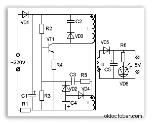
The device is a blocking oscillator operating in a self-oscillating mode. It is powered by a half-wave rectifier (D1, C1) with a voltage of approximately +300 V. Resistor R1, R2 limits the starting current of the device and acts as a fuse. The blocking oscillator is based on a transistor MJE13005 and a pulse transformer. A necessary element of the blocking generator is a positive circuit Feedback formed by winding 2 of the transformer, elements R5, R4 C2.
The 5v6 zener diode limits the voltage at the base of the MJE13005 transistor to within five volts.
Damper circuit D3, C4, R6 limits voltage surges on winding 1 of the transformer. At the moment the transistor is turned off, these surges can exceed the supply voltage several times, so the minimum permissible voltage capacitor C4 and diode D3 must be at least 1 kV.
PRACTICE.
1. Disassembly. Self-tapping screws holding the charger cover in this device They look like a triangular star. As a rule, there is no special screwdriver at hand, so you have to get out as best you can. I unscrewed it with a screwdriver, which, over the course of its use, had become sharpened into all sorts of crosses.


Sometimes chargers are assembled without bolts. In this case, the body halves are glued together. This indicates the low cost and quality of the device. Disassembling such a memory is a little more difficult. You need to split the body with a non-sharp screwdriver, gently pressing on the joint of the halves.
2. External inspection of the board. More than 50% of defects can be detected precisely due to external examination. Burnt resistors and a darkened board will show you the location of the defect. A burst case or cracks on the board will indicate that the device was dropped. Chargers are used in extreme conditions, so falls from anywhere are a common cause of failure.
In five out of ten memory systems that I had the opportunity to do, they were trivial contacts bent through which 220 volts are supplied to the board.

To fix it, just slightly bend the contacts towards the board.
You can check whether the contacts are at fault or not by soldering the power cord to the board and measuring the voltage at the output - the red and black wires.


3.
Broken cord at the output of the charger. It usually breaks at the plug itself or at the base of the charger. Especially for those who like to talk while charging the phone.
Called the device. Insert the lead of a thin part into the center of the connector and measure the resistance of the wires.
4.
Transistor + resistors. If there is no visible damage, first of all you need to unsolder the transistor and ring it. It must be borne in mind that the transistor
MJE13005 the base is on the right, but it also happens the other way around. The transistor may be of a different type, in a different housing. Let's say MJE13001 looks like a Soviet KT209 with the base on the left.

Instead I installed MJE13003. You can install a transistor from any burnt-out lamp - a housekeeper. In them, as a rule, the filament of the bulb itself burns out, and the two high-voltage transistors remain intact.
5. Consequences of overvoltage. In the simplest case, they are expressed in a short-circuited diode D1 and a broken resistor R1. In more complex cases, the MJE13005 transistor burns out and inflates capacitor C1. All this simply changes to the same or similar details.
In the last two cases, in addition to replacing the burnt conductors, you will need to check the resistors around the transistor. With the diagram this will be easy to do.
Now, more than ever, the number of gadgets per person has reached its maximum.
Phones, tablets, laptops, various wireless headsets - all this abundance of equipment has a power source and, accordingly, a charger for it.
The phone is not charging from the charger - what should I do?
Chargers are often carried with them in a bag or pocket, and so that they take up minimal space, their cords are twisted with a bend and tension.
This in turn leads to an almost invisible wire break and charging inoperability. Just break in the cord- this is the most common breakdown in these types of devices, and, frankly, it’s a pity to throw it away because of this.
Yes, you can, of course, buy a new one and not have to worry, but if the device is non-standard, for example, an old model phone, then it is not always possible to find such a charger. But at a flea market they might give you a block with the same problem, and no one needs the extra expenses.
Therefore, repairing a charger is a useful and worthwhile endeavor.
How to fix a charger for a phone, smartphone, tablet with your own hands
Below, this article will describe a simple repair method that does not require special equipment, which will give your charger a second life.
The photo shows a charger with a problem in the cord.
A cliff is not always visible to the naked eye. It can be hidden under the thickness of the main (top) insulation and remains almost invisible.
But, as practice shows, a fracture most often occurs near the entrance to the block or at the base of the plug.
To find the location of the break, just connect the switched-on charger to the phone and move the cord in a suspicious place.
As soon as you see that charging “started” for a moment, it means that there is a break in the place where you were moving at that moment.
In this case, upon closer inspection, the fracture and break were visible even without movement. It just happened to be at the entrance to the power supply.

The main problem in repairing such blocks is that they are not collapsible. Therefore, to get to the electronic board, you need to be careful and some effort.
Using a screwdriver and a knife, you need to pry up the base of the back cover and remove it.

You should pry where the cord enters the device. If the entrance is too tight, you can trim the rubber clamp slightly.

This must be done carefully so as not to cut the wire at all.
Using a screwdriver, we try to lift the lid up.

It may happen that it cracks in half, but more often, as in this case, the lid was removed entirely, without damage.

It was even clear that it had latches, and in the body of the charger there were recesses for them.
This means that after repair it is possible to put the cover in its place without using glue.
When the cover is removed, you need to pull the printed circuit board out of the case. Since it “sits” tightly, a screwdriver will help you get it out. By resting the blade of the screwdriver against the body and hooking its tip into one of the soldering points, we pull the board out.


The design of the case is such that when the board is inserted inside, its input contacts are connected to the clamps of the power plug pins. Therefore, when installing the board back into the case, you need to take this point into account.
The photo below shows the board with all its “internals”. The wires are soldered at the bottom.

View from the opposite side.

And here in the photo are the tracks for the input contacts.

The wire will have to be cut below the place where the damage is located. But it is very important to remember which wire is “+” and which is “-”. In some cases, the wires are color coded, with red being the positive wire and black being the negative wire.
When marking with color, you can safely cut it, and then simply solder the wires, observing the polarity.
In our case, the wires are the same color, but since the cord is flat, you can see which side of the cord the wire goes to negative and which to positive. Mark, and then cut.


Without losing the mark, strip and tin the wires on the cord.

We solder them to the board one at a time, observing the polarity.


On printed circuit board There is usually a polarity marking at the soldering point.

To prevent the output cord from dangling, we wrap a bandage of black electrical tape around its input part. The thickness of the bandage should be such that it fits into the slot for the wire and is fixed in it.


Before installing the cover, check the operation of the device. We plug it into the network and connect it to the phone. If the phone is on this moment If you don’t have it with you, we use a DC voltmeter.
Since the internal contact in the socket has a very thin tube, and the probe of the device does not go into it, you can use a piece of thin copper wire to check.

Having inserted it into the internal contact tube, we connect the probe of the measuring device to it and the outer terminal of the plug.
The voltmeter shows that voltage is present, which means that the fault has been fixed.

Now we snap the back cover.

We connect the phone and enjoy the results of the work done.

Greetings, radio amateurs!!! While going through old boards, I came across a couple of switching power supplies from mobile phones and wanted to restore them and at the same time tell you about their most frequent breakdowns and elimination of shortcomings. The photo shows two universal schemes for such charges, which are most often found:

In my case, the board was similar to the first circuit, but without an LED at the output, which only serves as an indicator of the presence of voltage at the output of the block. First of all, you need to deal with the breakdown; in the photo below I outline which parts most often fail:

And we will check all the necessary parts using a conventional DT9208A multimeter. It has everything necessary for this. A mode for testing diodes and transistor junctions, as well as an ohmmeter and a capacitor capacitance meter up to 200 µF. This set of functions is more than enough.

When checking radio components, you need to know the base of all parts of transistors and diodes, especially:


Now we are completely ready to check and repair the switching power supply. Let's start checking the unit to identify visible damage, in my case there were two burnt resistors with cracks on the case. I didn’t find any more obvious shortcomings; in other power supplies I came across swollen capacitors, which also need to be paid attention to first of all!!! Some parts can be checked without desoldering, but if in doubt, it is better to desolder and check separately from the circuit. Do soldering carefully so as not to damage the tracks. It is convenient to use a third hand during the soldering process:

After checking and replacing all faulty parts, do the first switching on through a light bulb, I made a special stand for this:

We turn on the charger through the light bulb; if everything works, we screw it into the case and rejoice at the work done, but if it doesn’t work, we look for other shortcomings; also, after soldering, do not forget to wash off the flux, for example, with alcohol. If all else fails and your nerves are on edge, throw away the board or unsolder it and take the live parts to stock. Good mood to everyone. I also suggest watching the video.