During the period of use of your car, the car radio is changed several times. There may be various reasons for this. Someone wanted best quality sound, for some it has simply broken down, while others follow fashion and simply want to update obsolete equipment.
To install a new radio, many people have to pay for a service at a car service center. However, you just have to find out the purpose of all the wires at its outputs and the purpose of all the plugs, and how to install the car radio will no longer be a difficult question.
Radio format
They come in single-block (or single-din) and double-block (double-din). These formats are designated as 1DIN and 2DIN, respectively. In Europe, single-din ones are common, but in America, Japan and Korea - double-din ones.

Recently, the need for two-block radios has increased, because The size of the case allows for additional multimedia functions. It is worth considering that.
Plugs with ISO markings
ISO marking is an international standard established for the production of car radios and vehicle wiring. In order to prevent equipment damage, it is prohibited to use the car and radio wiring for purposes other than their intended purpose. Almost all manufacturers of audio equipment equip these contacts with an adapter to the ISO standard.
There are various adapters for connecting and installing vehicle electrical networks to the ISO standard.
Each car brand uses its own plugs. In addition, adapters are produced, thanks to which you can switch to the ISO standard from the original pads. There are many adapters for connecting car electrical networks to the ISO standard. Adapters are also available for switching from the original car radio pads to the ISO standard.

Often, manufacturers of car audio equipment supply it with individual plugs, regardless of the international standard. But still, companies that respect their brand make sure that they have adapters for ISO standard plugs. If the car has standard wiring, everything is much simpler: all you have to do is use it to connect the car radio.
DIY car radio installation
There is one slightly “clumsy”, but very simple way to connect a new car radio. You are cutting the wires from the plug of your car radio or from the car wiring. Next, using electrical tape, connect the wires in accordance with the color pinout on the reel. The disadvantages of this method are that it is not entirely aesthetic. In addition, electrical tape is not a very reliable fixation for winter cold, as a result of which a short circuit may occur.
Application in in this case heat shrink tubing or clamp terminals can protect against problems.
However, if you still work hard and install ISO contacts, it will pay off in the absence of “headaches” during subsequent car radio changes.

You will only need to pull out the old car radio, switch the plug from it to the new one and install the new car radio in the niche.
Types of format according to the size of radio tape recorders
According to the size format, car radios are divided into two types: single-block and double-block. Since the international standard defines their designations as 1DIN and 2DIN, they are also called single-din and double-din. European car manufacturers mainly produce cars with niches for single-block car radios. Manufacturers from Korea, America and Japan specialize in two-block niches. These niches are 2 times larger than single-block ones. Two-unit car radios have a clear advantage in terms of multimedia functions. In this regard, the demand for them is constantly growing. Unfortunately, not everyone can install a two-unit car radio on their car, because... defines the corresponding type.
Basics of connecting a radio
So, the source of electricity is the battery. At the same time, it is also a source of danger for the radio and speakers. Under no circumstances should its plus be allowed to touch the minus of the car radio or any speaker terminal. In this case, it is recommended to power both the plus and minus from the battery. Often, car enthusiasts neglect this rule by using power from the cigarette lighter or ignition switch. Yes, this is probably easier, but... In the first case, we give the speakers the absence of interference and interference, as well as the ability to drive at full power.
The wire for connecting the plus requires a stranded copper wire with a cross-section of 4 m² or more.
It should be as short in length as possible. A fuse must be installed. It should have a face value of 10-20. And good insulation. It is installed at a distance of forty or more centimeters from the battery terminal. Sometimes the fuse is already installed by the manufacturer. The “—” wire should also be as short as possible.

The wires are laid carefully, avoiding twisting, at the greatest possible distance from other consumers. They are connected to the car radio after the speakers are connected. Do not allow the exposed positive battery cable to touch anything. It must be insulated until the last moment, when all that remains is to power the car radio with plus.
Connecting speakers
Very important point- this is a diagram of the installation of the car radio and the correct connection of the speakers according to the phases. The speaker terminals are marked, so you can easily figure out where the plus is and where the minus is. Usually the wide terminal is positive, the narrow terminal is negative.
It happens that cars of previous years have speakers that do not have terminals with markings. Then to determine the poles you need a regular battery. Connect its “+” and “-” to the speaker terminals. If the phasing is correct, the diffuser will move outward, and if it is incorrect, it will move inward.
Incorrect speaker phasing causes a loss of 80 percent of sound quality.
It can also lead to damage first to the speaker, and then to the car radio itself. If installed incorrectly, this is the most common mistake. It would seem that all the speakers are functioning, but there is no power or quality.
Let’s say that you don’t even have a battery on hand to check the phasing. Then, turning on the radio, output the sound, say, to the front left speaker, turn up the volume almost until hoarse, and then distribute it equally to both (i.e., set the balance to zero). If the sound power and low frequencies have undoubtedly increased, then the phasing is correct. Otherwise, you need to change the polarity on one (!) of the speakers. The same actions must be performed with the rear pair of speakers, as well as with the side pairs (rear left - front left and rear right - front right).

When, after making balance adjustments, the difference in sound is not noticeable, then do not suffer, leaving it as it is. Apparently, your hearing doesn’t really need this correctness.
Selection of wiring
The speaker wires from the car radio also have their own markings. As a rule, there are two or four pairs of them. A solid color without a black stripe is a plus. The same color, only with a black stripe - this is a minus.
A solid color is connected to the wide speaker terminal, a black stripe is connected to the narrow terminal.
The disadvantage for a pair of front or side speakers in an acoustic system up to 20 W can be common. In systems with 30 watts per channel or more, each channel has its plus and minus. It is prohibited to confuse them or swap them. It is also impossible to ground the speaker by connecting the minus to the car body. This will cause sound distortion, and the power cannot be increased beyond 30 percent. In low-power radios that have manual radio tuning, there may be 2 or four colored wires (acoustic with a plus) and not a single pair with a black stripe (negative). In this case, the “minus” for all speakers is connected to the main negative wire of the car radio (black), which, in turn, must be routed to the car body. (And even preferably on the negative terminal of the battery).

Almost all speaker systems are equipped with connecting wires. But these are not installation wires, but test wires. They are included so that you have something to check the speakers upon purchase, and not for use in a car. Their cross-section, as a rule, does not exceed 0.25 - 0.5 m²m. It is too small to pass the power supplied by the car radio to the speakers without any losses. These wires can be used only when the power of the installed speaker is no more than 15-20 W, and its diameter is 10-13 cm, that is, for auxiliary acoustics.
For main 40-100 W speakers with a diameter of 16 cm or more, special speaker wires are required. These are oxygen-free copper wires, directional. Their cross-section is from 1 to 4 m², depending on the power of the radio and its speakers.
For perfect sound great importance has even the direction of the coil of the copper beam.
In addition to the text, which is written on transparent insulation, arrows on such wires also indicate the correct direction to the speaker from the car radio.
Insulation requirements
The wires must have a good insulating layer, preferably silicone (the silicone layer does not burst in the cold). They also need to have a cross-section corresponding to the power. They need to be placed correctly around the cabin (not near the power wires of other consumers). It is necessary to prevent them from twisting (they have absolutely no need for extra length). They must be laid closed throughout the cabin.
The wires should not fray. They must not be easily touched by feet or come into contact with cargo in the trunk. In a door from its post, they need to be pulled through a hard cambric so that the hinge (of a fairly large diameter) moves in the body behind the door post (not in the door itself), and certainly not between the post and the door.
Speaker placement
Let's say for the rear main acoustics, oval speakers (16x23 cm) were purchased. Then, before installing the car radio and connecting it, so that the short axis of the loudspeaker is directed diagonally across the cabin (that is, the rear left one is towards the passenger, the left one is towards the driver). Do not cover speakers in the trunk with boxes or crates. They must “breathe” freely, and in a fairly large volume.
It is better to place tweeters (or tweeters) on the windshield pillars. The further you are from the low frequencies, the brighter the quad effect. Direct the sound from the driver's tweeter to the passenger, and from the passenger tweeter to the driver.

Video - installing a new radio
Conclusion!
Two-component systems are increasingly becoming fashionable. It is better to place their woofers not in the panel, but in the rear shelves or doors. And tweeters need to be placed further and in front. Tweeters sold separately, which do not require crossovers, can be paralleled with front or rear speakers, as they say, to taste. They have different powers - from a subtle squeak to real support for the entire spectrum of mid-high frequencies. Other speakers cannot be connected in parallel. If you really can’t bear to plug in a couple more, then install them in series with the existing ones.
Often, after purchasing a Sony radio, we start reading the instructions and realize that it doesn’t say anything more than how to set it up after installation. But it is important for us to know what the connection diagram for the Sony CDX-GT210, or xplod, GT200E, GT300EE, f7700, GT470UE and other models looks like, which in most cases the manufacturer is silent about. After all, its further operation depends on how correctly it is connected to the car.
Algorithm of actions
In fact, there is no difficulty in the process of connecting this equipment. The main thing is to carry out this task consistently and step by step, while knowing which connectors are needed for what. Depending on what model your device is, there are several components to connect:
Connectors (ISO connector)
It is the connectors and connectors that are the main components when connecting. They are made according to international standard(ISO) and strictly individual. If your car radio has a connector of the first type, then everything is simple, connecting will only take a few minutes.

The situation is completely different with the connector of the second type. In this case, to connect the device, you need to select an adapter for it or cut the wires, and then connect them to the individual connector block according to the diagram. Although, it is not advisable to cut the wires. In this situation, it is better to use heat-shrinkable tubes and other safety measures.
Wires
To pick up the positive wire, you need to have a certain skill. You definitely need to stock up on a fuse if you are going to connect the Sony CDX radio directly from the battery. We pay special attention to the diameter of the wiring. It should not be smaller than the main device connector. If this cannot be done, then you can connect the radio through the cigarette lighter. But this should be done only as a last resort. To minimize energy loss from the battery, you need to connect according to the order of these actions:
- Ground is the black cable that comes from the battery;
- The power or positive cable for twelve volts is the yellow cable that comes from the battery;
- The red cable is responsible for the signal to turn on the main device from 33 (ignition switch);
- Antenna for other devices – blue wire.
But if we touch on the question of what diodes to install, then in this case there is no difference, you can use any, such as KD522B.

Connector and shade differences
If you are going to connect the Sony radio yourself, the wiring diagram will ultimately look like this:
- The yellow power wire is responsible for the memory and power supply of the head unit. Therefore, initially it needs to be connected as a positive one;
- The red wire turns off the operation of the head unit, although it is also a power wire. It needs to be connected. According to the instructions, it must be connected to the ignition switch. If you do this, then the main device will also turn off when the ignition is turned off.
- It is not recommended to connect positive wires together. If you ignore this recommendation, the car radio will constantly work, and this threatens to quickly de-energize the battery, especially when the car engine is not running. Connecting a Sony xplod radio (video).

If you have a VAZ car, and you want to install a Sony car radio, for example, GT200E, then you can do it like this:
- l We connect the red wire to the fifth contact of the BSK column, and not to the ignition switch. Despite the fact that this scheme is original, it still has shortcomings. When a person sits in a car for some time, in order for him to be able to listen to music, he must not remove the key from the ignition. And with such a connection, electricity consumption increases;
- l Via a regular button. It is placed on a cable that has a red GU color. It has the usual functionality - turn it on or off. The GU works constantly in this situation. When the car sits for a long time, simply press a button to stop the supply of power from the battery.
- l Through the emergency gang. When we use it, the power supply to the GI will be provided by means of a constant plus. Power is supplied to the PG through a red cable from the ignition switch. In this case, the diagram will look like this:
- From the clock block, plus comes after ignition.
- Direct current flows from the cigarette lighter or battery.
- There is a ground wire coming from the cigarette lighter, which is black.
When the car has a two-wire solenoid that is triggered to open or close by changing polarity, then the connection diagram for the Sony CDX-s22 radio will look like this:
- When the car doors are opened, a positive charge is supplied to relay P1 from the solenoid. After it is triggered, power is drawn from the battery through the terminals of its contacts and relay P2. Thereby adding GI to the diet.
- Consequently, when the car door closes, the chain breaks, and therefore the power supply is turned off.

This scheme has many disadvantages, including due to the additional relay there is a large current consumption. However, when you bought a new car, or just want to change the radio, in order to do everything right, choose the optimal connection diagram for your case and follow it exactly. Then you will definitely succeed.
In contact with
How to connect a car radio yourself?
How to connect the radio yourself?
At Not correct connection, you risk, at best, getting a sound that is not of the quality and power that is expected, and at worst, ruining the system itself and the car.If this warning has no effect on you and you have a great desire and are determined to install an audio system in your car yourself, let’s try to find out how to do it correctly. Just “get acquainted”.
It is advisable to have a tester, screwdrivers and electrical tape. Installation time usually takes from 5 minutes to 5 hours.
The car in which the audio system is installed may have the following configuration options with conductors and connectors for the car radio:
- In the car, all conductors to the front and rear speakers are connected and routed. The power wires are removed from battery and the positive wire has its own separate fuse. All wires are connected to the connector and this connector coincides with the socket in the installed radio. The cord from the antenna is brought out and has a plug that also fits the installed radio.
- All the necessary wires, both power and loudspeakers, are installed and routed into the car. All wires are connected to the connector and this connector does NOT fit the car radio being installed.
- There are no conductors for the speakers in the car, the power wires are not routed out, or all the wires are there, but they are not connected correctly or have a lot of wear, tears, etc. In general, everything is bad here.
First option We won’t look at it, all you need to do here is connect and insert. It should only be noted that it would not hurt to check whether everything is connected as required by the new radio, and whether the wiring and speakers correspond to the power for which the new radio is designed. If something doesn't match or doesn't match, read on.
Second option. The car wiring connector does not match with the radio socket. The fact is that each manufacturer equips its audio devices with individual connectors for connection. And even various models from the same manufacturer have different connectors. However, a separate adapter for the so-called ISO standard is often supplied with car radios.
![]()
Therefore, before taking any action, make sure that the adapter is missing (which happens very rarely) or it also does not fit.
Then you can get out of this predicament in two ways:
The first, and most correct, is to purchase an ISO adapter for the electrical wiring of your car. There are a great variety of adapters on sale now, and you shouldn’t have any problems purchasing them.
The second method is undesirable and unreliable, but the most common among car enthusiasts and, unfortunately, among some technical centers. This method involves biting off the connectors and connecting the wires directly with twists. The first thing you need to do is make sure that the wires on the car connector (or connectors) match the color of the wires from the car radio adapter. If the wires match, disconnect the battery, and then use wire cutters to cut off the car connector and the connector included with the car radio.
You have to be careful with the car radio connector so as not to bite off the wrong thing. To avoid confusion, connect the connector to the radio and bite off the part that remains unconnected. We connect car wires and wires from a car radio according to color markings, and it is advisable to solder the connection points and insulate them with special heat-shrinkable casings.
If for some reason the colors of the wires do not match, then the next, very important step will be to test the wires and may have to connect the missing wires.
To do this, we arm ourselves with a tester or multimeter with a beeper and a 9-volt battery.
Let us remind you that all manipulations with the wiring must be carried out with the BATTERY DISCONNECTED!!!

We will not dwell in detail on the dialing procedure here, we will only say why a battery is needed here.
The fact is that if you ring the speakers without disconnecting the wires from them (and it’s so lazy to pull the plug again), you should have two wires ringing.
This is a pair of corresponding speakers. But to determine which of them is plus and which is minus, you will need a battery. Connect the battery to this pair, one wire to positive, the other to negative, and notice where the speaker cone goes.
If the diffuser moves out, then the polarity is correct, the wire that was connected to the positive of the battery is marked as positive, and the one that is connected to the negative is marked as negative. If the diffuser is pulled inward, then you need to mark the wires the other way around. You need to connect the battery to the speaker for no more than 1 second.
Main wires and their colors. |
||

Thanks to pleasant music, a good radio makes any trip more comfortable. Most used cars either do not have radios or CD players, or are equipped with cheap, low-quality devices. Therefore, the question of how to connect a radio in a car is relevant for many drivers. From the article you will learn how to connect the radio correctly and what safety measures are followed when doing this.
Basic parameters of radio tape recorders
Before you begin installing or connecting this device, you must determine the basic parameters that will affect all further actions. These include:
- size;
- power;
- shape of connectors.
Modern radios come in two versions: thin and thick. The first ones are also called single-block, they comply with the 1DIN standard. The second ones are called two-block, they comply with the 2DIN standard. Most European cars are equipped with a 1DIN socket, so installing a two-block device into it is impossible. American or Asian cars are often equipped with 2DIN sockets, so installing thin devices in them is possible, but you will have to work hard.
The second important parameter is the total power, which is the sum of the power of all channels. Correct determination of power is necessary for correct calculation of current consumption and wire cross-section. In this case, the power supplied and consumed differs by 1.5–2.5 times. That is, to provide an output power of 4x20 watts, you will need not 80 watts, but at least 150. With this power, the current passing through the wires reaches 12–13 amperes.
The more powerful the sound-reproducing device, the thicker the wires are needed to connect the battery or speakers.
Alternating current, which is the basis for the operation of speakers, further increases the requirements for wires, because electrons move most actively along the outer surface of the metal. Therefore, it is necessary not only to increase the thickness, but also to use multi-wire twisted cable. The output power of each channel of the device should not exceed the power of each of the speakers. If the output power is higher, you will have to install more powerful speakers and lay new wires of the appropriate thickness.
Most manufacturers of car audio equipment equip it with unique proprietary connectors, which do not always correspond to the contacts installed in the car. These connectors consist of two parts: a plug and a plug. The contact connection diagram (pinout) depends on the manufacturer and is indicated in the documentation for the radio and the car. If the package includes an adapter for a standard ISO 10487 connector, then connecting the car radio does not cause any particular problem. If there is no such adapter, you will have to independently connect the plug corresponding to the car plug.
Preparatory actions
To properly connect the radio, you need to perform preparatory steps. After making sure that the radio is the right size, you need to check whether the wire cross-sections and the plug match the plug. To correctly determine the cross-section, take into account the following: 1 mm² is capable of transmitting 4–5 amperes of direct or current without problems. That is, for a current of 10 amperes, the cable cross-section should be 2–2.5 mm². To properly connect the speakers, use single-core copper wire in soft insulation, with a minimum diameter of each wire and an optimal cross-section. The smaller the diameter of the wires in the core, the greater throughput and less power loss at high frequencies.
Prepare your tools. You will need:
You will also need:
- soft copper single-core wire with a cross-section of 1.5 mm²;
- a fuse whose current is 1.3–1.5 times greater than the maximum current consumption;
- insulating tape;
- heat-shrink tubing.
Wiring
To correctly route the wiring to the battery, use the holes in the wall of the engine compartment through which the wiring harnesses pass.
Do not under any circumstances connect the plus power supply of the radio to the plus of the ignition switch. The wire feeding the ignition switch is not designed to handle that kind of current, so turning on the sound-reproducing device at full volume will overheat it.
As a result, the wire will melt, a short circuit will occur and, in the best case, you will have to change the ignition switch and the ECU (electronic control unit) of the engine. In the worst case scenario, there will be a fire in the car.
To connect to the battery, use special terminals; they are sold at any auto parts store. Don't forget to put a fuse in the plug-battery circuit. It is advisable to install it in the engine compartment, not far from the battery. This will make it easier to replace if the fuse blows for some reason. To connect the wires correctly, use a soldering iron or crimp terminals and heat shrink tubing. Do not twist them; over time, the resistance of such a contact will increase, which is why it will begin to heat up very much. Heat-shrink tubing protects the joint more effectively than electrical tape, and is easier to work with. You need to put them on the connection and heat them with a lighter.
When starting to install new wires and cables, disconnect the battery. This will protect the car from short circuit, damage to electrical and electronic equipment or fire. Attach new cables to the body or wiring harnesses laid in the engine compartment. This will increase the length of the wires, but will save you from many problems. After all, a dangling wire gets frayed and can end up in the wrong place and interfere with servicing and repairing the car.
Fix a new wire to the standard wiring harness or body every 20–30 cm. After you have inserted all the new wires into the plug or plug, assemble them into a single bundle using plastic clamps. This harness should connect the plug to all areas where the wires will go to the side. This will protect the plug or plug from broken wires.
If you install more powerful speakers along with the radio, then they will require laying new wires that will match the cross-section. Use hidden routing; to do this, lay all wires under the front or side panels, rugs and other decorative elements. Do not neglect to secure the wiring, otherwise the wire may come out over time, after which the likelihood of chafing or breaking increases.
Connecting connectors
For this operation you will need electrical diagram machine indicating the pinout (contact numbers) of the standard connector for radio equipment. If the plug and plug do not match, then change the connector on the sound-reproducing device. It doesn't matter which side you put the plug on, as long as it matches the plug perfectly. Do not fit the car plug into the radio. If you decide to replace the plug, you will have to resolder the car connector. If you have the required plug or plug with wires already connected, then simply solder them to the corresponding wires of the sound-reproducing device. If the plug or plug is without wires, then use a thin needle to pull the contacts out of it, insert the stripped wires into them, crimp them using a special tool or pliers and insert them into the corresponding hole in the connector.
Conclusion
Now you know how to connect a car radio, and you can install it in your car yourself. The pinout of the contacts of the sound-reproducing device and the car, as well as the connection diagram, are described in detail in the instructions for their maintenance and repair, so read these documents carefully.
Sony car radio connection diagram and setup
Sony car radio connection diagram
The connection diagram for a Sony car radio implies the correctness of actions, knowledge of the purpose of the connectors and much more. This article will tell you how to install and connect car radios from this company. Sony car radios and a connector connection diagram are all that is needed to carry out the process correctly.
Connection
There are several components for connecting car radios. Let's look at them.
Connectors
First of all, the important components when connecting are connectors or connectors. They can be individual or ISO, that is, made according to an international standard.
The differences between them are as follows:
- If the connectors (see Connector for speaker cable and why it is needed) are individual, then you need to select an ISO adapter for them or cut the wires, and then connect them to the individual connector block according to the diagram.
Note. On the other hand, cutting the wires and making connections in the manner described above is highly not recommended. It will be better to use shrink sleeves and other precautions.
- As for the ISO connectors, they are much more convenient. If the Sony car radio is equipped with them, then connecting it will be a matter of minutes.
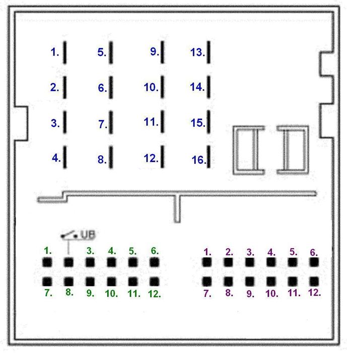
Sony car radio connector pinout
Wires
Correctly connecting the positive wire is also very important. If you connect a Sony car radio directly from the battery, you will need a fuse. In this case, the diameter of the wiring is also extremely important, which should not be smaller than the head unit connector.
Note. As a last resort, the car radio can also be connected through the cigarette lighter.
To reduce energy leakage from the battery, the connection is made according to the following scheme:
In this case:
- The black cable coming from the battery is ground;
- The yellow cable coming from the battery is 12 V power or positive;
- The red cable is responsible for the signal to turn on the head unit from the 3Z*;
- Finally, the blue wire is the antenna or other devices.
Note. As for diodes, you can install any type KD522B.
*ЗЗ – ignition switch

Connector for sony car radio and pinout by color
The wires when connecting the car radio should be located according to the following diagram:
- The yellow power wire is always responsible for powering the head unit and its memory. First of all, it should be presented as a plus;
- The red wire is also a power wire, but it turns off the head unit. It must also be submitted.
Note. The instructions state that the red wire must be connected through the ignition switch so that the head unit turns off after the ignition key is turned.
The positive wires are often connected together. They twist and connect to DC, but this is not recommended.
The fact is that in this case the head unit will work constantly, regardless of whether the key is turned in the ignition or not. In turn, this threatens to de-energize the battery in a matter of time, especially when the car is stationary.
If the Sony car radio is connected to VAZ models, then the process can be carried out as follows:
- Connect the red wire not to the ignition switch, but to the 5th contact of the BSK block.
This scheme is original, but has disadvantages. So, if a passenger remains in the car for a while, then you have to leave the ignition key with him so that he listens to music. In addition, such a circuit consumes much more electricity.
Three connection scenarios
Schematic diagram of Sony cdx car radios
The most correct connection diagram for a Sony car radio can look like three ways.
Regular button
- Connection via a button, which is placed on the red cable GU. It is normal - on/off.
With this connection, the PG works constantly, and if the car is parked for a long time, you can simply press the button and stop power from the battery.
Emergency crew
In this case, we don’t mean a regular button, but a car’s emergency lights:
- When activated, power is supplied to the PG through a constant plus;
- If the button is not pressed, then power is supplied to the PG through the red cable from the 3Z.
The diagram will look like this in this case:
- The Sony car radio has a backlight wire that connects to the cigarette lighter light;
- The plus after ignition comes from the clock block;
- Direct current is supplied from the battery or cigarette lighter;
- The black ground wire is also pulled from the cigarette lighter.
Via solenoid
If the car has a 2-wire solenoid that is activated to close/open by changing the polarity, then the circuit can be arranged like this:
- When the car doors open, a positive pulse is sent to relay P1 from the solenoid. It is triggered and begins to take power from the battery through the terminals of its contacts and relay P2, thus connecting the GU to the power supply;
- During closing, relay P2 is activated and the power supply is interrupted, the GU is turned off.
Scheme with big amount cons. Increased current consumption due to additional relay.
Troubleshooting a Wrong Connection
If you bought a Sony car radio and need to connect it instead of the standard one, or you have become the owner of a car where the control unit from this manufacturer is not connected correctly, then these instructions will help you fix everything.

Car radio connector pinout
So, it often happens that a Sony car radio is connected “without a key”. In other words, the connection was made directly from the battery, without an ACC wire.
In addition, the confusion of wires in the circuit can lead to a situation where one of the front speakers plays and one of the rear speakers plays. All this is corrected like this.
Removing the radio:
- The mass is removed from the battery so that while digging in the wiring it is not accidentally shorted;
- The insert on the center panel box is pulled out and pulled up from the front;
- The screws located above the climate control control console are turned out (at least this is the case on many foreign car sedans);
- The ashtray is removed;
- The front panel of the Sony car radio is removed from the mounts and then moved to the side;
- 4 screws fixing the central blocks are removed;
- The car radio is removed.
- There are a bunch of wires behind the radio that need to be studied according to the connection diagram for the control unit with ACC (see above);
Wiring

Sony car radio connection diagram
- In addition, you need to study which wire goes where;
- If you believe this wiring diagram, then just swap the green and white wires to solve the problem with the speakers;
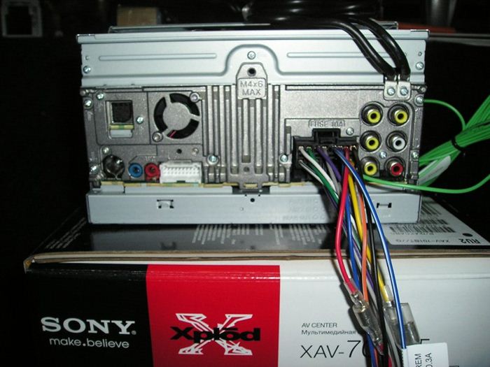
- In the photo below you can see that the small chip on the left is responsible for the rear acoustics, and the large chip with 8 wires (on the right) is for power and front;

Sony car radio wires
- You should also pay attention to the fact that the radio is connected with 2 positive wires: one of the wires is yellow and the other is red. They are connected together and connected to DC current, bypassing the ignition switch, as here;

Yellow and red wires together
Note. As a rule, the black wire is responsible for ground, brown or yellow for constant power, pink with a blue stripe for power from the lock. The remaining wires go to the front speakers.
- The red wire breaks, and the insulation from the wire with the blue stripe is unscrewed. The two wires are twisted together and insulated;
- All wires are wound back. Don't forget to swap the white and green wires going to the speakers;
- The GU is connected and everything is checked like this: if the key in the lock is in position 1, the radio is turned off, if the key in the lock is in the ACC position, the radio is on.
Note. The wires must be cut using heat shrinks. During this operation, you can at the same time adjust the control panel to the woofer at the rear. It will be enough to pull out the cup holder and run the wire to the subwoofer under it. That's it.
Now, dear reader, you know what all the intricacies of connecting a radio mean, at least in theory. As for practice, there is no need to rush to start it until you have reviewed the review on the topic, studied the diagrams and photo materials in detail.
When working with your own hands, you must not forget that the wires must be well insulated. Independent troubleshooting and the ability to connect a car radio is a valuable thing.
Now you can save on expenses that are inevitable when calling a specialist, the price of whose services sometimes causes confusion among most Russians.
http://avtozvuk-info.ru