A modulated infrared signal is used to transmit commands. A digital code characterizing the function selected by pressing the corresponding key is sent by the remote control in the form of a series of “flashes”. Each "flash" contains a sequence of short pulses. The digital code about the selected command is formed by the duration of the interval between “flashes”. IN in this case The duration of the gap is measured between the leading edges of two adjacent “flashes”. Logical “0” corresponds to a period of 2 ms, and logical “I” - 4 ms.
The function of 1C 1001 is to generate a keyboard scanning signal, decipher information about the pressed buttons and output a digital code corresponding to the selected function from output 20. The operation of 1C 1001 is determined by the quartz clock generator XI 001.
The output signal D 1001+D1002+D 1003 is a sequence of bursts of IR radiation pulses, the intervals between which are determined by the transmitted code. It should be noted that typical remote control circuits have a transmitter reference frequency of about 250 kHz, and a less common one is about 450 kHz. The frequency is changed so that the operation of the remote control does not interfere with the operation of other components of the TV.
2.2. Troubleshooting remote controls
Before you begin troubleshooting the remote control system, you need to determine that the problem is with the remote control. The situation is easiest with remote controls that have an indicator LED, by the operation of which you can judge the serviceability of the remote control. Unfortunately, not all remote controls have such an indicator. You can quickly and reliably pre-check the operation of the remote control using a video camera, in the viewfinder of which you can observe the presence of flashes of infrared radiation. It is also advisable to check whether the control button on the TV control panel is stuck in the pressed position - in this case, the remote control is blocked. A faulty remote control is usually also indicated by the inability to perform one or more functions and a decrease in the distance from which you can control the TV.If you have determined for sure that the remote control is faulty, and not the receiving part of the system, then first you should install a known-good battery. If the operation of the remote control has not been restored, you should not keep a new battery connected to the remote control circuit for a long time, as due to possible short circuit in a circuit it can quickly fail.
Rice. 2.1. PANASONIC TX-32WG25C TV remote control diagram
Troubleshooting in the remote control circuit (Fig. 2.1) can be performed in the following sequence.
Dimension 1
Connect a known-good battery to the remote control circuit and check the supply voltage level at pin 22 of the 1C 1001. The absence or strong drop in the supply voltage level at this pin indicates a probable failure of the 1C 1001 controller microcircuit or the smoothing electrolytic capacitor C 1001. Poor contact in battery compartment. If the supply voltage corresponds to the nominal voltage, thenDimension 2
Check the supply voltage level at the same pin 22 of the 1C 1001 controller by pressing a key on the remote control panel (or short-circuiting the corresponding contacts on the printed circuit board). In the absence of even a small change in voltage, we can talk about the inoperability of the circuit (most likely a break in the emitting diode). In this particular remote control circuit, a break in one of the diodes will be less noticeable than in remote controls that use two, or even more so one, emitting diode. This effect also occurs when there is poor contact in the keyboard, therefore, if the supply voltage does not change when closing the contacts of one key, you should check by closing the contacts of other keys.If the supply voltage drops significantly when you press a key, then most likely the controller chip IC1001 needs to be replaced.
If the supply voltage drops slightly when you press a key, you can
Dimension 3
By closing the contacts of any key, you should check the presence of the controller output signal at test point TP4. It is impossible and does not make sense to determine which digital code is being transmitted, however, the very presence of pulses usually indicates the serviceability of the 1C 1001. If there is no signal in CT TP4, aDimension 4
Using an oscilloscope, you should check the operation of the quartz oscillator of the controller chip. The absence of oscillations in CT TP2 and CT TRZ is a sign of inoperability of the controller or quartz resonator XI 001. It is wiser, of course, to first replace the resonator and only after a negative result of such a replacement - 1C 1001. In this circuit, it will be useful to check the serviceability of C1003. Having thus ensured that the IC1001 controller is in working order, you can performDimension 5
You need to use an oscilloscope to verify the presence of a signal at the base and collector of the output transistor Q1001. Based on the results of these measurements, we can conclude that it is serviceable.If the above checks do not produce a positive result, then, in the unlikely event, the keyboard controller IC is producing incorrect digital codes or, more likely, there is an open in the circuit board trace from the output transistor collector to the emitting diode.
Rice. 2.2. Diagram of the receiving part of the remote control of a 14-inch SONY TV with OSD circuit
2.3. Troubleshooting remote control receivers
Modern converters of infrared radiation into electrical signals, used in televisions and other devices with remote control, are a chip, in the housing of which there is an IR radiation detector and a shaper amplifier, which, as a rule, has three terminals: “power”, “output” and "general". As an example in Fig. 2.2 shows the remote control receiver of a SONY TV. As can be seen from the figure, the signal from the remote control receiver is directly fed to the control processor 1C 103 for processing.Testing the remote control receiver (sometimes called the head amplifier) is straightforward. You just need to make sure that the supply voltage and output signal are available. Let us remember that this signal is a stream of serial data, and using an oscilloscope it is impossible to determine the reliability of the transmitted data. digital code. However, if there is a signal, then it can be assumed that the transmitted code is correct and malfunctions in the remote control system are associated with incorrect operation of the control and monitoring circuit. If there is no output signal, before replacing the CHIP, be sure to check the operation of the remote control receiver by disconnecting its output from the TV circuit. There is, although rare, the possibility that the corresponding input of the control microprocessor is “shorted”.
We would also like to note that an indirect sign of a failure of the remote control receiver, with a known working remote control, is the flawless control of the corresponding functions from the front control panel of the TV.
2.4. Displaying service information on the TV screen
In this section we will look at circuits that provide the output of various service information to the TV screen, i.e. OSD (On Screen Display) circuits. These circuits provide functions that allow you to make various settings on the TV using various information displayed on the TV screen. It should be noted that if previously in ordinary mass-produced TVs, using OSD signals, as a rule, only the channel setup menu and data for operational adjustments, such as volume, brightness, contrast, saturation, shutdown timer (SLEEP), audio channel blocking ( MUTE), etc., then in modern TVs, using various on-screen menus, you can carry out not only operational settings, but also perform automatic testing of the components and circuits of the TV, call up various service modes and work in them (for example, in the factory adjustment mode you can execute initial setup TV), display the current calendar, time, etc.2.4.1. Basic principles of OSD operation
As has already been said, everything modern televisions have certain OSD circuits. In many TV models from various companies, OSD signals are generated by a character generator located directly in the central control microprocessor, following commands from the remote control or the front panel of the TV. Synchronization of these signals is carried out by horizontal and vertical sync pulses supplied to the central microprocessor.OSD circuits also often use a separate character generator chip, with the help of which a sequence of video pulses is generated, which, after mixing with the main video signal, leads to the display of a particular character on the screen - numeric, alphabetic or graphic. This chip receives a clock signal from the same source as the scan generators, so the characters appear on the screen motionless and in a strictly defined place.
Some OSD circuits have the ability to control the positioning of characters on the screen. The microprocessor determines which characters should be output, and it, in turn, receives commands from control buttons or from the remote control. Some of these commands are hard-coded into the microprocessor ROM in the form of subroutines.
2.4.2. Typical OSD circuits
In Fig. 2.3. shows the OSD diagram of a 21-inch SONY TV using a separate 1C 102 character generator chip. Please note that the OSD diagram shown in this figure is practically no different from that shown in Fig. 2.2, where IC104 serves as the character generator.
Rice. 2.3. OSD circuit for 21-inch SONY TV
Despite the fact that the OSD functions are performed by 1C 102, it is controlled by the central microprocessor 1C 101 via the CLOCK (pin 7), DATA (pin 5) and CS (pin 14) lines. Synchronization of the OSD signal is carried out in 1C 102 using vertical and horizontal sync pulses tied to the beginning of the vertical and horizontal blanking intervals and formed from the reverse pulses of the vertical and horizontal scanning of the TV.
The clock signals for the 1C 102 are generated internally, and their frequency is determined by the values of the capacitances and inductors connected to pins 1 and 13 of the 1C 102. Note that L102 is configurable so that you can change the frequency of the clock signal on pin 13 of the 1C 102. This way you can set the position displayed OSD characters on the kinescope screen. The data bits for IC102 come from the processor IC101. They are sequentially transmitted to pin 15 of IC102 and synchronized by a signal at pin 16. The display processor IC102 receives data only when there is a low logic level at pin 14 CS.
The signal generated in IC102 in accordance with the data received from IC101 is fed to the “green” cathode of the kinescope from pin 6 of IS104, through the Q104 buffer to the video processor. As a result, all OSD characters, numbers, etc. appear bright green on the screen. (Note that there is big number OSD circuits, where signals of other primary colors - red (R) and blue (B) - are used to display service information.
When moving from channel to channel, the central microprocessor 1C 101 generates a positive blanking pulse at its 24th output. The blanking pulse mutes the sound and blocks the output signal from the video processor. A blanking pulse is also supplied to pin 17 of 1C 102, removing OSD signals from the “green” cathode of the kinescope.
Internal clock frequency 1C 102 is synchronized by vertical and horizontal pulses arriving at pins 18 and 20 of 1C 102.
Remember how in the cartoon “Three from Prostokvashino”, Uncle Fyodor’s mother said: “I’m so tired at work that I can’t even watch TV!” Apparently, this phrase is the answer to the question why all modern household equipment has infrared remote controls (RC). But, if you look at it, it all started much earlier.
Remote control with wires
The first work on remote control was carried out by the Germans in the late 30s of the twentieth century, even before the start of World War II. The object of automation was tube receiver. The control panel was a separate metal panel with buttons. Pressing the button led to the activation of an actuator - a relay, electromagnet or motor. The connection between such a remote control and the receiver was made with a multi-core cable, which still tied the listener to a specific place.
Soviet first-class tube TVs had similar remote controls. It was a small plastic box with a volume control, connected to the TV with a wire. Apart from the volume, such a remote control could not control anything. But such a remote control undoubtedly created certain conveniences. After all, back then there were no annoying advertisements and you had to watch the film from beginning to end.
Ultrasonic remote control
The first wireless remote control owes its appearance to the American Hasso Plattner. In 1972, after leaving IBM, he organized his own company and, in order to establish business contacts and connections, often traveled extensively around the world. At one of the meetings with the management of JVC, an embarrassing incident occurred.
While discussing some problem, Plattner stood up and moved towards the TV to point out some detail on the screen with his finger. But he didn’t reach the screen, tripping over the remote control cable. He spilled a cocktail on his suit and said angrily: “Wasn’t it possible to switch channels via radio wave?”, which made the Japanese companions blush. And exactly a year later the first remote control using ultrasonic rays appeared.
The principle of its operation was to supply its own frequency when you press each button. The ultrasound was captured by a microphone and amplified by an amplifier that used several parallel channels with resonant circuits. Control voltages appeared at the outputs of these channels. With this method of encoding channels, not much was obtained.
Further development of electronics, in particular the emergence of INTEL microcircuits, made it possible to abandon such multi-frequency coding. At one ultrasonic frequency due to in various ways modulation made it possible to transmit many more commands than with multi-frequency coding. One of the first devices equipped with an ultrasonic remote control was a TV from RCA. Commands were encoded using pulse width modulation (PWM).
These remote controls had a number of shortcomings. First of all, large dimensions and power consumption. This was due to the fact that ultrasonic radiation is readily absorbed by household items - clothing, upholstered furniture, carpets. Therefore, the radiation power had to be increased, which shortened the battery life.
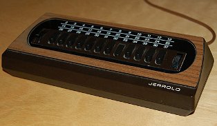
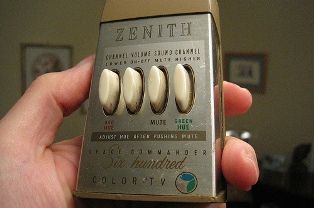
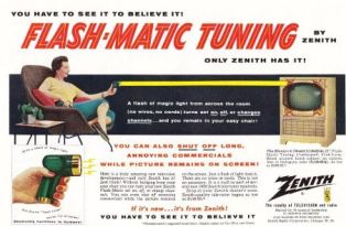
Rice. 1. The first remote controls
Specialized microcircuits for remote control
Things got better after INTEL developed its first microprocessor, the 8080. This new development was taken as a basis by GRUNDIG and MAGNAVOX, which made the first specialized microprocessor. In this case, the processor generates required code digital command under the influence of a pressed button. Thus, a specialized microcircuit for the remote control is nothing more than an already flashed program. Such remote control units were called TELEPILOT.
IR remote control
The first color TV with microprocessor control and an infrared remote control was released jointly by GRUNDIG and MAGNAVOX already in 1974. Already in this model, the number of the switching channel was shown in the corner of the screen (OSD system). This command system is called ITT. This was the first-born of the GRUNDIG company.
Subsequently, research in the field of remote control was carried out by PHILIPS, which developed the RC-5 command system. New system allowed the encoding of 2048 commands, which was 4 times the number of commands in the ITT system. The carrier frequency was chosen to be 36KHz, which did not interfere with the transmissions of European broadcasting stations and the operation of remote controls with ultrasonic transmitters with a frequency of 30 and 40KHz, and also ensured a sufficient reception range.
But electronic technology did not stand still, but, as one movie character said, it moved forward by leaps and bounds. Televisions were improved, VCRs and stereos, satellite tuners, CD and DVD players and much more appeared.
To control the new equipment, new remote controls were also required, and accordingly new microcircuits had to be developed. Such microcircuits were developed by SIEMENS and THOMSON. The carrier frequency of the new remote control was also 36 KHz, but a different method of signal modulation was used - two-phase modulation. With this modulation, the carrier frequency was more stable, which ensured increased range, increased noise immunity and operational reliability.
PHILIPS again made a further contribution to the development of remote control systems. At the beginning of the 90s of the last century, it combined all the best that was in the RC-5 and SIEMENS systems. The resulting product was called the “Unified Command System.” Its essence is as follows. The remote control of such a system has the functions “MENU 1” and “MENU 2”. In each of these functions, the same button performs different commands, and it turns out that more commands can be performed with fewer buttons.
Subsequently, control panels penetrated into many other areas of household appliances. IR radiation is currently used to control air conditioners, fans, wall heaters, etc. Even some models of car radios and digital cameras have remote controls.
With all the variety of remote controls and devices they control, they all work almost the same: when you press the buttons, the infrared LED of the remote control emits packs of infrared pulses (flashes), which are received by the photodetector (“eye”) of the TV or other device. A modern integrated photodetector is a rather complex device, although you cannot tell from its appearance. The appearance of the photodetector is shown in Figure 2.
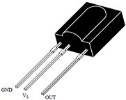
Figure 2. Photodetector
The receiver is configured to receive pulses with a carrier frequency of 36 KHz, which corresponds to the RC-5 protocol. If you simply turn on an IR LED near the photodetector, for example, from a battery, then its non-blinking glow will not have any effect on the “eye”, even if this LED is brought close to the photodetector. Also unaffected by daylight and artificial light. This selectivity is due to the fact that there is a bandpass filter in the photodetector signal amplification circuit. Structural scheme photodetector is shown in Figure 3.
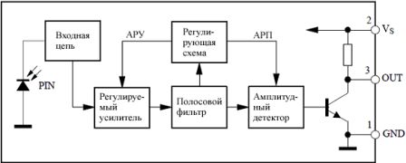
Figure 3. Block diagram of the photodetector
The RC-5 protocol will not be explained in detail here, since this ignorance will not affect the further story, and indeed the repair of the remote control. Those wishing to get acquainted with the RC-5 protocol in more detail can find its description on the Internet. This is a topic for a separate article.
Remote control device
With all the variety of modern remote controls, all models are designed almost identically. The main difference is most often appearance,in the design of the device. As was said in the first part of the article, the basis of a modern remote control is a specialized microcontroller. The program in the MK is written during the manufacturing process at the factory and cannot be changed later. When included in the circuit, such a microcontroller requires a minimum number of attachments. The diagram of a modern remote control is shown in Figure 4.
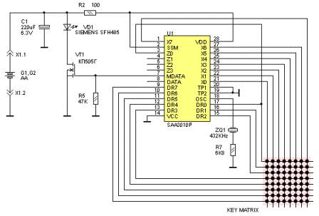
Figure 4. Diagram of a modern remote control
The basis of the entire device is a U1 type SAA3010P chip. Although the letters may be different, which indicates a different chip manufacturer. But the numbers still remain 3010.
As mentioned above, there are practically no attachments. First of all, this is, although this is not entirely accurate. Its purpose is to synchronize the internal oscillator of the microcircuit, which provides the required timing characteristics of the output signal.
The lower right corner of the diagram shows the key matrix (KEY MATRIX). Its rows are connected to pins DR0...DR7, and columns, respectively, to pins X0...X7. When you press any button, one column-row pair is closed, and a pulse sequence corresponding to the pressed button appears at the output of the microcircuit. Each button produces its own sequence and no other! In total it is possible to connect 8*8=64 buttons, although in practice it may be less.
The output signal in the form of voltage pulses is sent to the gate field effect transistor VT1, which in turn controls the operation of the IR LED VD1. The control algorithm in this case is very simple: the transistor opens - the LED lights up, the transistor closes - the LED goes out. In this case, they say that the transistor is operating in switch mode. As a result of such flashes, pulse packets are formed that correspond to the RC-5 control protocol.
The circuit is powered by two AA type galvanic cells, the energy of which lasts for at least a year. There is an electrolytic capacitor C1 in parallel with the batteries, which bypasses the internal resistance of the batteries, extends their service life and ensures normal work Remote control with slightly low batteries. An LED in pulse mode can consume current up to 1A.
After considering the remote control circuit diagram, it seems we can say that it will break down with such simple device absolutely nothing, but it’s not true. It is the remote control that most often causes trouble for the TV owner. How to repair the remote control, what its main “diseases” are, as well as how and how to cure them will be discussed in the second part of the article.
IN general case remote control (RCU) - a wireless or wired device designed to control any mechanism, object or process from a distance. All remote control devices are divided into groups:
- according to the method of receiving power: via cable, autonomous;
- via the channel used to transmit control signals: IR, ultrasound, radio, wire, mechanical drive;
- in terms of functionality: with one set of commands, universal for several devices from the same manufacturer, programmable (teachable);
- by mobility and other characteristics.
The most common type of remote control nowadays is a mobile stand-alone wireless device that controls objects via an infrared (IR) channel. It is this type of remote control device that we use in everyday life when we transmit control signals to a TV, air conditioner, stereo system, player and other household appliances.
The first models of remote controls contained a minimum of control elements only to perform basic functions. Over time, the approach has changed: modern products have a full set of control elements, while the controlled devices themselves contain a limited set of them.
Remote control device
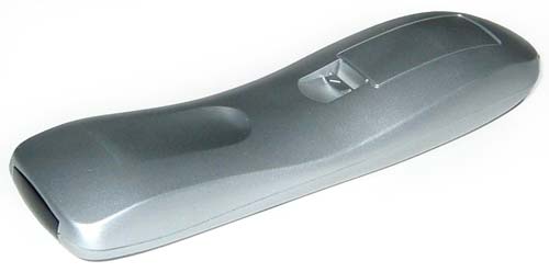
The gadget is a small oblong plastic box. On its front part there are buttons with which you can select a control command.
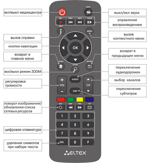
At the end of the device there are holes for the IR emitter lens, which directly sends the command for execution. On the reverse side, under the cover, there is a niche for installing batteries. As a rule, these are two AAA batteries.
If we disassemble the remote control by disconnecting its upper part from the lower part, we will see two more elements. First - printed circuit board with contact pads and mounted electronics. 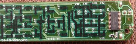 The second is a pad made of soft elastic material with convex control buttons with conductive disks.
Infrared wireless remote control: operating principle
The design of the remote control and the operation of the remote control are based on one-way or two-way transmission of information between the remote control and the controlled object using light rays in the infrared range. IR receivers and transmitters are used to receive and transmit signals.
The remote controls that control air conditioners have a circuit with a two-way information transmission channel: a control signal is sent to the air conditioner, and the operating parameters of the unit and temperature data are returned back.
All other models are overwhelmingly single-channel.
Sending and receiving commands
Let's take an operation that is most often encountered in everyday life: remote wireless control TV. The first thing the remote circuitry does is determine which button was pressed. The determination principle is the same as in computer keyboard: Scan a matrix of button placements. But, unlike the PC keyboard, the remote control scan generator is in standby mode and turns on only when you press the buttons on the remote control. This achieves economical use of batteries.
Then the control signal (command) is encoded and transmitted by an IR LED. Before transmitting the main signal, the transmitting and receiving devices are synchronized, and the remote control code is checked on the receiving side for compliance. The transmission itself will continue as long as the control button is pressed.
It should be noted that manufacturers electronic devices are not limited in any way in creating algorithms for encoding control signals and used modulation frequencies. This leads to the fact that often even models of the same type from the same manufacturer require different control panels for control.
Remote control diagram
Most circuits of TV remote controls and other household devices are based on the basic microcircuit, generating a control signal after pressing the corresponding key, signal amplifier And IR LED. The difference lies only in the name and layout of the radio elements inside the device body and on the printed circuit board.
![]()
The microcircuit is a specialized microcontroller into which data is recorded during the production process. program code. The recorded program then does not change during operation. The board also contains quartz resonator to synchronize the frequency of the receiver and transmitter. The signal amplifier is part of the microcircuit or is made on a separate element.
To create such a device yourself, in addition to amateur radio skills, you also need to be able to create program code for microcontrollers.
Remote control for PC
Remote control for personal computer may be useful when working with the interface, both operating system, and when managing the functioning various programs. For example, managing presentations in Power Point or playing media content in Media Center. Sometimes such remote controls are already included with the PC.
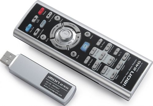
Manufacturers of remote controls for PCs, unlike TV ones, have implemented 2 solutions: IR and radio remote controls. The fact is that when controlled in the infrared range, it interacts with the device with direct visibility and at a distance of up to 10 m, which is sufficient for TV, but may be inconvenient for controlling a PC, especially during presentations. The radio remote control increases this distance to 30 m, regardless of obstacles in the signal path.
Externally, the radio remote control will differ from the IR remote control only by the presence of a small antenna. But in order to be able to carry out control, the PC needs one more element: a radio or IR signal receiver installed in the computer or laptop. This can be either a built-in device or a module connected to USB port. The second option is preferable.
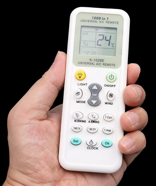
Universal and/or programmable remote control
A universal remote control may be required in two cases:
- A replacement has not been found for a lost or broken old TV remote control or other household appliance.
- A lot of different household appliances in one room makes controlling them from different remote controls extremely inconvenient, since the concept of “correct design” and “optimal ergonomics” is different for all manufacturers.
There are two types of such devices: remote controls that store commands (learning ones), and programmable universal remote controls. In the first case, the standard remote control of the TV or other device is used to enter the required codes. In the second, the list of available codes and models of equipment that can be controlled is in the instructions for the control device. The difference is that despite the thousands of device models supported universal remote controls, the required device may not be on this list.
“Training” of memory remote controls is carried out in accordance with the user manual and using the original remote control. If the purchased remote control has fewer keys on its front panel than the “native” one, then first of all you should program only those that are necessary.
After purchasing a universal multifunctional remote control, you should not throw away the old standard ones. Firstly, they may be required if the new one suddenly fails. Secondly, the universal one may not have some of the necessary elements. And thirdly, they may be required for reprogramming in the event of a failure or battery change.
Smartphone as a remote control
Another option for a remote control for almost any device is to use a smartphone as a control device. At the same time, it may or may not implement signal transmission in the IR range (technology IrDA). In the latter case, control is carried out via Bluetooth or Wi-Fi. The only limitation is that the controlled device must also support these information exchange protocols, which is not implemented on all equipment.
More interesting as a remote control is the version of a smartphone with an infrared port. Let's look at this using the model as an example Xiaomi Redmi 3 and a pretty old TV Daevoo. We will need to install from Google Play special application. It can be anything, the main thing is that the list of supported equipment includes a model of the control object. For this phone with shell from MIUI it's called Mi Remote(Russian language is present).
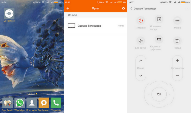
After installation, the desired manufacturer is selected, and full TV management is performed.
Conclusion
Thus, we found out that failure of the remote control for any equipment is not fatal. You don’t even have to repair it, but simply replace it with a similar one or purchase a universal one. As a last resort, temporarily, you can use a smartphone.