Naturally, every user who is a little familiar with the device of electronic equipment and knows how to hold a soldering iron and a screwdriver in his hands has a desire to fix the monitor on his own.
- If the monitor does not turn on, and even the indicator light does not light up (usually located near the power button or right on it), most likely the problem is related to monitor power failure. Consistently check the presence of voltage in the outlet from which the monitor is powered (you can check it by plugging an ordinary desk lamp into the outlet), the operability of the power cable (you can check it by disconnecting the cord from the monitor and connecting another device with it, for example system unit computer), the reliability of the cable connection to the monitor (perhaps the contact is broken and the cable just needs to be inserted more tightly). If all these measures did not help, you will have to carefully open the monitor case and check the power supply.
- If the monitor turns on, but there is no image, then the reason may not be in the monitor, but in the computer's video card or the monitor's connection to the video card. Check whether the monitor interface cable is connected to the video card, whether both ends of the cable are firmly inserted into the connectors. Try connecting a different monitor to your computer. If it works, then the problem is in your monitor, if not, the video card is most likely faulty.
- If the monitor turns on, but the image is distorted, or appears and disappears from time to time, then the reason may be in the electronic “stuffing” of the monitor. Carefully open the monitor case and carefully inspect the electronic components. If there are elements with a “swollen” or smoked case, there are burnt contacts or places on the boards, then this is probably the reason for the malfunction of the monitor, try replacing the failed electronic elements with new ones.
Remember that in any case the most reliable way repair the monitor - contact a specialized service center.
Probably, many are familiar with the problem of loss of touch sensitivity. screen on the PDA. In the event that you consider it not economical to carry it for repair in service center and think that you can repair it yourself, then this article will help you.
You will need
- A small Phillips screwdriver and a hex screwdriver, plus a stationery eraser and tape.
Instruction
Free workplace from extra items. Prepare a box for storing the bolts so that they do not get lost. Separate the sides. Unscrew the two bolts under the sidewalls and two bolts at the bottom of the rear cover with a hexagon. Also unscrew the bolts in the battery compartment. In the place where you removed the sidewalls, there are latches. Pry off the top cover with a screwdriver. Unplug connector screen and unscrew the two screws located at the top with a Phillips screwdriver. In the right upper corner The board has a headphone jack. There is a microphone underneath. Release the connector from the case and separate the board from screen.
Clean the contacts of the cable with an eraser - they will begin to shine. Flip the screen. Connect the shield to the board. Next, you need to enable this design. Attach the battery to the board with adhesive tape. For this design to work, you need to remove the lock, which is located between the CF connector and the battery. Press the Power button on the board.
Typically, the breakdown is
Monitor repair. Repair practice. Do-it-yourself monitor repair
Objective: Learn how to repair the monitor, what parts need to be replaced when the monitor breaks down
Theoretical information:
Distortion of the image on the top of the screen: lines are "knocked out", shifted within a small range
The malfunction occurs only at a frame rate of 100 Hz at a resolution of 1024 x 768, or at a frequency of 120 Hz at a resolution of 800 x 600.
Replacing the diodes and capacitors (1 uF x 50 V) in the gate circuit of the field-effect transistors of the S-correction of the raster did not give a result. Monitoring with an oscilloscope the S-correction signals coming from the microcontroller and the keys on field-effect transistors (opening-closing) showed that all elements are operational.
The reason turned out to be the increased voltage ripple of 13 V, which is generated by the power supply for the vertical scan driver. This was caused due to the "loss" of capacitance of the filter electrolytic capacitor in this circuit.
Progress:
LG FB770G-EA (CA-113 chassis)
When turned on, the monitor works, but when it is switched to standby mode (power saving mode is turned on), it does not switch back to working (when a video signal appears)
At the same time, the green LED on the front panel is flashing, the power supply is working, the DPMF & DPMS microcontroller pins are low potential.
Replacing the synchroprocessor (TDA 4841), reset chip (KIA 7042), 12 MHz resonator and EEPROM (2408) did not work. Replacing the microcontroller solved this problem.
LG T717BKM ALRUEE" (chassis SA-136)
No line sync (see Figure 1). Synchronization is only available in 1024 x 768 (85 Hz) mode, and a black horizontal stripe 0.5 cm wide appears on the top of the screen. Synchronization is also absent when the signal cable is disconnected. Replacing the microcontroller, EEPROM chip, filter capacitor in the B + circuit did not give any result. After replacing the capacitors C604, C605, C602 (external circuits of the synchroprocessor), synchronization was restored.
Samsung SyncMaster 797DF" (chassis LE 17ISBB/EDC)
The device does not turn on
The control of the power supply showed that the rectified mains voltage is supplied to the IC601 controller, but there are no secondary voltages at its outputs. After replacing the IC601 chip, the monitor's performance was restored.
Quite often in monitors of this type, the rectifier diode in the secondary circuit of the 14 V power supply fails. As a result, the IP controller switches to protection mode and there are no secondary voltages at the unit output.
LG Flatron T710BHK-ALRUE
When the monitor is turned on, the power supply protection is triggered
All output voltages are greatly underestimated (within 2…4 V), and the voltage at the output of the 50 V channel is 10…20 V. The PWM transistor of the B+ Q719 controller is very hot.
Together with it, the filter capacitor C744 (47 uF x 160 V) is also heated. Checking the elements of this node revealed a faulty diode D710 (UF 4004) - a short circuit. After replacing it, the monitor works fine.
Abnormal image size horizontally
The problem was solved by replacing the LM358 chip (installed in the horizontal size correction circuit).
Samsung 959NF" (chassis AQ19NS)
20-30 minutes after the monitor is turned on, the image shows a line shift, and not over the entire raster and with different shift values
Checking the filter capacitor in the mains rectifier, the sweep synchronization circuit with the power source showed that everything is normal. The filter capacitor C650 (100 uF x 16 V) installed at the output of the voltage regulator 5 VIC650 turned out to be faulty.
A similar defect often appears in the Samsung SyncMaster 757nf (AQ17NSBU/EDC chassis).
Samtron 56E (PN15VT7L/EDC chassis)
When turned on, a high appears for a second and protection is triggered
The control of the elements of the secondary rectifiers, TDKS showed that everything is normal.
If you disconnect the 50 V voltage circuit from horizontal scanning, the protection does not work.
After replacing the filter capacitor C407 (150uF x 63V), the monitor started working.
Samsung Syncmaster 750p
The image is fuzzy, doubles, and the defect appears even on the OSD image and when the video signal source is turned off. When connected to a computer for some time (about 5 minutes), the image is normal, then a failure begins: at first the image begins to "twitch" along the lines, then the lines shift horizontally relative to each other and the "twitching" stops.
The reason turned out to be the voltage filter capacitor B + C402 (10 uF x 250V). It is installed at the output of the DC / DC buck converter on transistor Q403.
The monitor does not work, the LED on the front panel is blinking (the glow color is green)
Control of secondary circuits showed the presence short circuit on in the horizontal power supply circuit. The PWM controller transistor B + Q719 (breakdown) and the filter capacitor C740 (leakage) turned out to be faulty.
LG T730PHKM (CA-139 chassis)
When the monitor is turned on, the LED on the front panel lights up and goes out after 2-3 seconds. Horizontal scanning does not start at this time (no high voltage). All voltages of the power supply are normal, the replacement of the microcontroller and the firmware of the EEPROM did not give a result
Monitoring the signals at the microcontroller outputs showed that there is a low potential at one of the K1 keyboard connection inputs, although not a single button is pressed (there should be a potential of 5 V). The reason turned out to be a factory defect: the head of the self-tapping screw that fixes the keyboard board closed the K1 bus to ground. After installing the dielectric washer, the monitor started working
Samsung SyncMaster 757NF
Missing image. All secondary voltages of the power supply are normal, except for 6.3 V. The output of this channel is only 3.8 V, and if you turn off the kinescope board, the voltage returns to normal - 6.4 V
The reason for the defective capacitor C642 (1000 uF x 16 V) is the loss of capacitance. After replacing it, the image appeared.
Compag p110, Sony gdm-5OOps
The monitor does not turn on, the indicator on the front panel blinks
The safety resistor R617 (0.47 Ohm) in the 200 V voltage circuit turned out to be open. After replacing it, the monitor worked, but the horizontal raster size was reduced. In addition, a vertical raster distortion (S-shaped) appeared. All secondary voltages of the PSU were normal, including 200 V.
A faulty capacitor in the dynamic focusing unit C717 (22 microfarads x 100 V) was determined by element-by-element testing. After replacing it, the image became normal.
Samsung SyncMaster 750s (chassis dp17ls)
The image is "blurry". If you adjust the Screen and Focus potentiometers on TDKS, that is, a normal reaction, the brightness and focus change independently. Supply voltage is normal. EEPROM firmware did nothing.
Sometimes this happens if you mix up the wires during the repair, through which the focusing voltages F1 and F2 are applied to the kinescope board, but not for this case. After swapping these wires, the image became a little clearer, but still not normal. It turned out that the wires F1 and F2 are not soldered to the kinescope panel, but are fixed using spring contacts. After disassembling and cleaning these contacts (there were traces of corrosion), the image returned to normal.
Horizontal size not adjustable
The adjustment signal is supplied from the microcontroller to the base of the Q714 transistor, but is absent on the collector. The element-by-element check revealed a faulty transistor Q707 in the S-correction circuit. The diode in the gate circuit of this D707 transistor also turned out to be faulty. After replacing these elements, the horizontal size began to be regulated.
Do-it-yourself monitor repair:
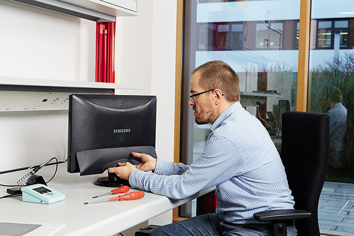
1. First stage: Opening the monitor and initial inspection of the internal components.
First of all, you need to disconnect all cables from the monitor. For some monitor models, the signal cable has a permanent external connection to the monitor.
Most LCD monitors the body consists of a front frame and a back cover, which often serves as the basis for the entire structure. It should be noted that there is no one recommendation for all designs and each manufacturer has its own characteristics that are unique to certain models.
Before starting the opening, it is necessary to take care of a flat surface (for example, a table) and a soft material that covers the flat surface and prevents scratches. LCD matrices. It is also necessary to organize sufficient lighting of the workplace. In order to disassemble the monitor, you will need to separate the stand bracket from the case by unscrewing the mounting screws or self-tapping screws. You will need Phillips screwdrivers, type PH1, PH2, and for devices from some manufacturers, you may need types in the form of a six-pointed asterisk. It is convenient to use a universal bit holder with a set of interchangeable bits of different sizes and types.
After unscrewing and removing the threaded fasteners, it is advisable to remember which fastener was screwed into which hole. The next step is to separate the front frame from the back cover. You should pay special attention to the fact that in many designs - the front frame is attached to the back cover by means of plastic latches. We do not recommend using a slotted screwdriver, a kitchen knife and other unsuitable items at this stage in order to avoid deformation of the case, the appearance of scoring and chips. We do not recommend applying excessive force if the front frame "does not lend itself" to separation. Careless movement and excessive, misdirected forces can cause irreparable breakage of the latches, which in turn will lead to unnatural gaps and change appearance your device.
After separating the front frame, it is necessary to disconnect the connectors of the high-voltage wires on the inverter board that go to the LCD panel. We do not recommend pulling on the wires to avoid breaking the conductors, but removing the high-voltage wire connectors with special tweezers.
There are four main components of the LCD monitor:
Power supply that provides power to the signal processing unit, LCD module and high-voltage converters (inverters)
A node of high-voltage voltage converters (inverters) for supplying CCFL backlight lamps.
Signal processing unit. In multimedia monitors, the signal processing unit is much more complex and contains large quantity elements.
LCD module. The device of the LCD module is described in the article "How the LCD module of the monitor works"
Before starting the search for the cause of the malfunction, an initial inspection of the assemblies should be carried out to identify elements with a changed shape, as well as darkening on the boards, indicating the heating of the components. If a component heats up until the board material underneath turns brown, it may indicate a component failure or a failure in the circuit to which the component belongs.
2. Second stage: Determination of the cause of the malfunction
To determine the cause of the malfunction, you will need a device diagram (or service manual), a multimeter with continuity functions, measuring DC voltage and alternating current, capacitor capacitance measurements, as well as an oscilloscope (a digital oscilloscope with memory may be required to diagnose the signal processing unit)
3. Third step: Replacing defective components
A temperature-controlled soldering station may be required to replace defective components, and a dedicated hot air soldering station may be required to replace signal processing assembly components. Note that some microcircuits are sensitive to excessive heat and can fail if overheated. Also, overheating of the pads and tracks should not be allowed, since excessive heating can lead to delamination and breakage of the conductor on the printed circuit board. In the event of a malfunction of microcircuits in BGA and FBGA packages, infrared soldering equipment with an appropriate set of stencils, as well as a special flux, may be required.
4. Fourth stage: Post-repair testing
After replacing faulty components, post-repair testing is a mandatory step. The testing phase will require an electronic thermometer, a DC voltmeter, an ammeter, and a test signal source. The minimum time for testing a restored monitor, according to statistics from practice, is at least 12 hours. In cases of troubleshooting that manifests itself with warming up or is of an unsystematic nature, the testing time should be increased to 20-30 hours. Testing should take place under the constant supervision of a specialist.
5. Fifth stage: Assembly of the monitor
The assembly of the monitor should take place in the reverse order of opening. Particular attention should be paid to the screwing force and the length of the screwed screws and self-tapping screws. If the screw or self-tapping screw turns out to be longer, then there is a danger of damage to the body elements and the LCD panel.
Within the framework of one article, it is impossible to describe all possible design features and methods for restoring monitors, and in each specific case, the path to finding the cause of a malfunction is unique. Sometimes an engineer with many years of practical experience has to strain his head to understand the design and circuit design.
Conclusion: In the course of practical work, I studied theoretical material, learned how to repair a monitor and learned what parts to replace when a monitor breaks down, how to repair a monitor with my own hands.
How to repair a monitor?
Master's response:
Did your monitor start to malfunction or stop working altogether? First, unplug the device from the mains, that is, unplug the monitor cable from the outlet. Also disconnect the cables from the monitor that are connected to the back of the monitor.
If you have a CRT modification of the monitor, then first remove the high-voltage charge from it with a thin screwdriver with an insulated handle: ground the sting and put it under the rubber cap that supplies voltage to the kinescope anode from a horizontal transformer.
Now wipe off the dust with a cloth, and additionally vacuum the monitor. Make a visual inspection, during which carefully look for cracks, darkening, short circuits and kinks in the conductors.
Next, you need to remove the power supply with the board from the mount. Check the integrity of the printed wiring. If you find oxidized contacts on the chip and the board, thoroughly clean these contacts and solder them.
The weakest point of CRT monitors is a line transformer, in which a short turn-to-turn circuit often occurs, which causes destruction of the winding insulation, overheating of the coil or its complete combustion.
And the most common problems with LCD monitors are problems with cables leading to the matrix. It is the loops, or rather their poor contact, that leads to interference throughout the screen. Although sometimes the cause is dead electrolytes-capacitors.
Lack of contact of the decoder loop with the matrix controller chip or one of the decoders is unusable, leads to vertical and horizontal stripes on the screen.
Is the screen covered with randomly running stripes? The reason for everything is a problem with the power supply of the matrix or incorrect operation of the DC converter. If the screen simply glows white, then power has been lost in the DC converter or matrix circuit. Most likely, the matrix fuse has blown.
Replace the backlight if the sensor is backlit unevenly or even with some color cast. Lamps must be replaced even if the backlight goes out regularly. Try soldering the lamp connectors. Sometimes the reason for the short circuit of the transformer lies in the malfunction of the backlight lamp.
If the firmware has crashed on your monitor, then you need to reflash it using a suitable programmer.
To make trouble with your monitor less frequent, follow the basic requirements: the monitor should not stand near open window and at the heating battery; ventilation openings must not be covered. Try not to smoke or cook near the monitor. If you plan not to use the monitor for a while, cover it with a cover.
Previously, monitors were "eternal": in most cases, they were used for several generations of computers, and they were changed only because fashion dictated devices with a larger diagonal.
The situation has now changed. Many displays begin to deteriorate after only four or five years of use. Perhaps LCD or TFT monitors are more vulnerable than CRT models. Or manufacturers began to develop their devices in such a way that they do not work forever, thereby taking care of continuous sales.
Incorrect design leads to heat locks
Visited our test lab Samsung model 226BW. Four years ago this monitor was an inexpensive quality product and very advantageous offer. On technical Internet forums, you can find information that this display fails, as a rule, after three to four years of operation.
It all starts with the fact that after turning on the image on the screen periodically shrinks to the center and flickers. However, after a while the picture will stabilize. Gradually, the flicker period increases, and the image ceases to stabilize.
Our model is no exception. The seller's and manufacturer's warranty has long ended, giving the monitor for repair would be too expensive and possibly more expensive than buying a new device. In most cases, this means a direct road to the landfill. We decided to open the monitor to determine the cause of the breakdown and fix it.
Since all the symptoms point to a problem with overheating and the power supply, we have concentrated on the components of the power system and related elements. And they saw the following: three electrolytic capacitors had suspicious swellings on the upper side (see Fig. 6).
The question is why Samsung engineers placed heat-sensitive components so close to the cooler. We believe that the board has enough free space to place the capacitors away from the heat source.
We decided to replace these components. Three 820 microfarad (25 V) capacitors cost about 100 rubles, and delivery costs will be 300 rubles - if there is no radio parts store nearby. Twelve touches with a soldering iron (desoldering and soldering) - and your monitor is "in service" again.
How to fix a Samsung 226BW monitor
 | 1. Remove the back coverRemove the plastic cover that hides the connectors and power supply of the monitor by simply pulling it towards you. |
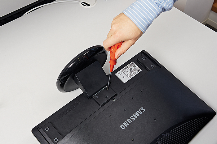 | 2. Remove the standThe monitor stand is secured with three screws. Rotate the device with the screen facing down and remove the screws. |
 | 3. Opening the caseGently depress the latches around the entire perimeter of the device and remove back wall. The metal cover, which you will see when you open the case, is fastened with latches and can be easily removed by hand. |
 | 4. Disconnect the plugDisconnect the plug on the right side (if the monitor is in front of you and the connector panel is "looking" at you). |
 | 5. Disconnect the rest of the plugsOn the left side, two other plugs are hidden under a metal cover. Pry off the cover with a screwdriver and remove it from the mounting holes. |
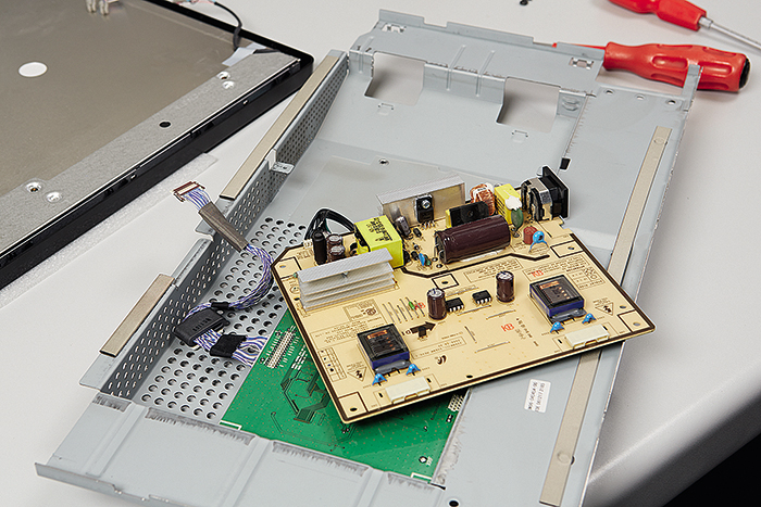 | 6. Remove the power supply housingCarefully remove the monitor power supply housing, and then determine the state of the capacitors near the cooler. |
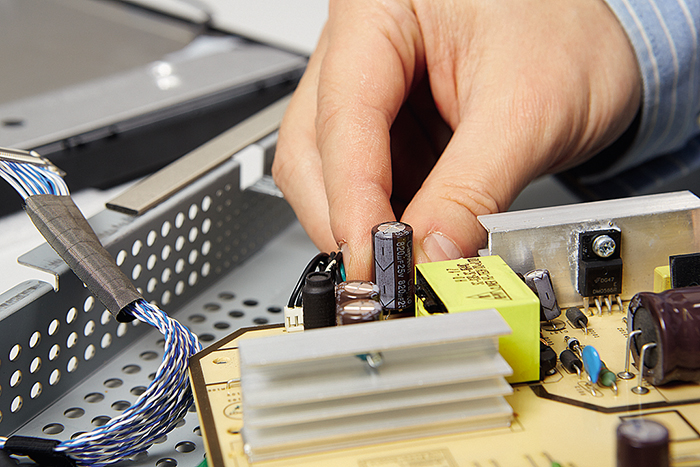 | 7. Replacement of deformed partsYou can see the bulge on the capacitor with the naked eye. For reliability, replace all three local capacitors - C110, C111, C112. |
 | 8. Soldering and assemblyWhen soldering, observe the polarity (a long contact tab, as a rule, “plus”). After that, install the power supply board in place and assemble the monitor back. |