Today, almost all homes are connected to cable or satellite television, and almost all channels are in good quality. But what to do if you are just renting an apartment? This is where a homemade antenna will come to the rescue. digital television- as a reliable and inexpensive alternative to the factory one. Read on to see how it is done.
To make this device, you will have to use 550 by 70 mm plywood, several self-tapping screws, and a forty-centimeter copper wire 40 cm long (the central core is 4 mm in diameter).
The base of the product is a board. Next, cut 8 pieces of wire, the length of which is 375 mm, while they should be stripped in the center by 20-30 mm. This is necessary to ensure good contact in signal transmission.
Now, cut out 2 wires, the length of which is 220 mm and, based on the dimensions of the board, they should be cleaned where the connections will be. After this, the remaining wires (eight pieces) need to be bent so that they acquire a “V” shape.

An antenna for digital television is absolutely no different from a regular decimeter antenna.
First, you should start purchasing a special plug, after which it should connect the antenna and cable. This is easy enough. Using a benchtop soldering iron, the plug is attached to the wire. This cable is installed over the bottom connection of the instrument. At this stage, the production of the antenna can be considered completed. It is already ready to be turned on.

An antenna for digital television is absolutely no different from a regular decimeter antenna.
The second method of making a digital television antenna from cans
Here, we will not use a ready-made device as a basis. The device will be completely assembled from available materials. A homemade antenna for digital television is made using:

- wooden trempel;
- adhesive tape or tape;
- soldering iron;
- two tin cans;
- several meters of wire (about 3-5 m);
- plugs.
First, you need to modify the standard television cable. To do this, you need to slightly cut its soft shell. Under the shell you will see a silvery “foil”. This material covers the cable in several layers. For this reason, in order to see the wire itself, you will have to cut about 10 cm from the edge. After this, you should twist the foil layer in order to make a sample of its middle layer by about 10 mm. The reverse end of the cord is equipped with a plug used to connect to the TV.

We're done with the cable, the banks are next. If we talk about sizes, then a tin container with a volume of 750-1000 mm is enough to receive a digital signal. The end of the wire with the “foil” is attached to one can (otherwise, the display of channels will be incorrect). The cable core is screwed onto the second can. It is preferable to connect the cable and cans by soldering. If the wire is secured with tape, most likely the product will not work.
The only option for using such material is when the cans are installed on top of the trempel. However, even here one cannot deviate from the technology of application. Namely, the arrangement of the cans should form a straight line. Tin containers should be located at a distance of about 7-8 cm from one another.
That's all, the homemade antenna for digital television is ready. Now you can start searching for a suitable signal and securing your device. Such an antenna will allow you to view several channels, up to 10-15, if the signal is not password protected.
Video: homemade antenna for digital television
If you live in the city, then you don’t necessarily need to have a large and bulky TV antenna, much less throw it on the roof and pull the cable. Digital television channels of the DVB-T2 standard can be perfectly received in the room, since the power of the transmitting towers is quite enough for reliable reception. I'll show you how to make a miniature home antenna of the Biquadrat type in 15 minutes. I also call it the Kharchenko antenna. This master class will save you from buying expensive Chinese analogues.
Typically, such structures are calculated using 1/4 wavelength. Such an antenna will receive all channels well even outside the city at a considerable distance, but at home (in the city) its size may seem a little large. And in fact, such sensitivity will be of no use. You can reduce all dimensions by half and take 1/8 of the wavelength as a calculation. The current antenna will be very tiny, but with sufficient sensitivity.
Will need

Making a miniature home antenna for digital television
The antenna circuit itself. This is perhaps the simplest and most common option, and we will make it even smaller.
We take the wire and, without removing the insulation, bend two identical squares with sides 67 mm with pliers.

We solder the joined ends and peel off a little insulation from the middle and tin.

Then, solder the socket on small wires. Using a utility knife, make cuts in the lid for the shoulders of the vibrators.

Fill everything with hot glue.

In the second cover we drill a hole for the socket and also glue it in with hot glue. We connect the covers and solder them with a soldering iron to make one whole. The antenna is ready.

Everything fits in the palm of your hand, so with the question “Where should I place it?” There shouldn't be any problems.
Result of work
We connect and direct to the tower.
I will compare the antenna with the same one, only full-size at 1/4 wavelength.

The level sensor will be a Chinese set-top box for receiving digital television.
Result:
- Classic Kharchenko antenna 1/4 wavelength, the set-top box gave - 40% sensitivity.
- Our reduced 1/8 wavelength version is 22% .
- And for comparison, let’s plug in a regular piece of wire - 1% .
At home, the antenna performed excellently. All channels are caught and received steadily, just like the full-size version. I recommend it for repetition.
Digital encoding of the television signal allows it to be delivered to the receiver while minimizing any losses. To support the technology, the TV needs an antenna for DVB-T2. Making such a device with your own hands is much cheaper than buying a ready-made one, paying about 3 thousand rubles for it. Terrestrial digital television displaces all similar types of signal transmission, while offering high-quality broadcasting and a variety of channels.
Changes on air
Making an antenna for an old-style tube TV was considered prestigious in its time and showed the level of skill, in modern world Interest in homemade devices does not fade, and many people make DVB-T2 over-the-air antennas with their own hands. Manufacturers of industrial equipment adapt to the changed reception conditions by connecting modern electronics to standard well-known designs, completely ignoring the fact that the main condition for the operation of the antenna is its interaction with the terrestrial signal.
In recent years, almost all broadcasting takes place in the DVB-T2 range, which reduces the cost and simplifies, from an economic point of view, the antenna-feeder system of transmission stations. Periodic maintenance requires less highly qualified personnel, and their work becomes less harmful and dangerous.
Television broadcast transmitters cover all large cities and sparsely populated villages with signals, so catching waves from unattended low-power stations in remote areas becomes important if you install an antenna for DVB-T2 reception, made with your own hands from scrap materials.
Due to the expanded construction of reinforced concrete buildings within the city, the conditions for signal propagation in populated areas have changed significantly. Multi-storey buildings with metal frame They are a kind of mirrors that reflect waves several times until they are completely attenuated.
There are many TV channels broadcast on the air today. A digital signal differs from others in that it either exists or it doesn’t; there is no middle position. Other transmission systems differ in that the channels perceive interference differently, which reduces their broadcast quality, and sometimes the image may simply disappear. A self-made antenna for DVB-T2 will allow you to receive the same signal for all channels that show the same high-quality picture.
The digital broadcasting signal is special in that it is not affected by interference; if it is one and a half decibels higher than the noise, then good reception is achieved. Signal dropout is affected by cable mismatch or phase distortion at any point in the transmission from the camera to the tuner, and the image can be scattered into small pieces even with a strong signal.
Basic features for making an antenna
Before making DVB-T2 with your own hands, you should study the principle of its operation.

For catching digital signal required, which can be very simply constructed even from a simple cable, having made the correct calculation.
The theory says that digital signals are easily transmitted in the UHF range and can be received by any type of antenna, but in reality this does not always work out.
You can make a television antenna yourself with minimal costs and without the help of strangers, but it should be remembered that the resulting device is inferior in reception quality to professional devices.
Requirements for antennas
New conditions for broadcasting, distribution and on-air reception have changed the basic requirements that DIY TV antennas must meet. DVB-T2 has abolished the previously significant directional and protective coefficients. In modern devices they do not matter, since the air is polluted, and even small penetrating interference can only be dealt with using electronic means. At the same time, the antenna's own gain (GA) plays an important role.
An antenna that tracks the air well has a power reserve for the received signal, which allows the electronics to sift it from interference and noise. A modern antenna for DVB-T2, made with your own hands, preserves electrical parameters in a natural way, and does not adapt to acceptable parameters using engineering techniques. It is consistent over the entire operating frequency range without the use of balancing devices.
Antenna amplitude and frequency characteristics
The antenna is made as smooth as possible; phase distortions arise due to sharp emissions and dips. Single-frequency antennas are stretched to an acceptable noise-to-signal ratio, thus allowing them to receive up to 40 channels. But they are additionally equipped with matching amplifiers, which absorb waves or distort phase indicators.

Most effective digital antenna DVB-T2 is made by hand:
- frequency-independent - with low performance, but cheap and easy to manufacture, constructed in a short period of time, intended for reception in relatively clean air on a short distance from the transmitting station;
- periodic band, catching all waves in space, ideally sorting them, which has a simple design, ideally works in tandem with a freeder throughout the entire reception range.
If we talk about design, the simplest DVB-T2 antenna is made by hand in the “eight”, “Polish” and “square” versions.
Figure-of-eight antenna
Refers to easily constructed devices, made like a standard figure eight, from which the reflector is removed. The ideal material is an aluminum strip, corner, tube, tire, or other profile. The top dimension is 140 mm, the side length is 130 mm, but these dimensions are given as a guide; during manufacturing they should not be kept exactly to the millimeter.
To begin with, cut a wire 112 cm long, begin to bend the first part 140 mm long, of which 130 mm goes to the antenna, and 10 mm remains for the loop. The next two sections are bent equally to a length of 140 mm, the next two - 130 mm, the next pair - 140 mm, then another 140 mm, then - 130 mm and make a second loop. The connections are pre-cleaned, connected and soldered; they are also contacts for fastening the cable core.
Stripping the cable and plug is done using a scalpel and a file. After soldering, the joints are sealed and secured with glue from a hot gun. If we talk about the plug, then the glue is poured into the solder joint, then into the cavity of the cap, the excess is then removed. The joint is assembled so quickly that the adhesive mass does not harden. The result is an eternal, strong and elastic connection. To make contact, we strip the ends of the cable from the plug side by 1 cm, from the antenna side by 2 cm.
When connecting by soldering, a do-it-yourself indoor digital DVB-T2 antenna is also sealed with glue, where it is recommended to install a rigid frame at the point of contact according to the size of the joint. If the device is made for yourself and will be rigidly fixed during operation, and transfer is not needed, then the frame is not made. A device made of this type easily picks up digital signals in the direct line of sight of a television tower at a distance of up to 10 km when installed outdoors.

Using a “Polish” antenna
The “Polish” antenna received its name during the times of the former Soviet Union as a reliable device for receiving signals from Soviet television, as well as channels in the UHF range. Digital broadcasting is practically not received on it due to its low efficiency. Some amateurs are trying to bring the design to ideal by shortening the long decimeter mustache and removing the reflector. In some cases, such a change allows you to adjust the image in digital format, but it is impossible to guarantee a reliable result. Speaking about Polish devices, we can note the high-quality operation of the amplifier, which works effectively with a digital signal.
Antenna type "square"
This DIY indoor DVB-T2 antenna is a modified copy of the standard design, known as “three squares,” which has six components and a matching transformer. A homemade antenna of this type confidently copes with receiving digital TV channels at a distance of up to 10 km in a straight line; for longer distances a signal amplifier is required.
The antenna design is simple to implement. The main structural element consists of round aluminum wire and single-core wires. The wire is bent to obtain six squares and a matching tap is made, which is a transformer high frequencies so that the signal matches the cable and the DVB-T2 antenna with the amplifier. With their own hands they solder the wires to the points, wrap them with copper wire and tin them with a soldering iron.
The cable is attached to the antenna with special clamps or using ordinary insulating tape. The cable is connected by placing a support, using a wooden plank or other material. When installing indoors or outside a building, the main condition is precise alignment with the television tower. This is done using a navigator; if there is no line of sight, the direction is clarified until the effect of receiving a powerful signal.
Antenna made from beer cans
The technology for manufacturing such an effective antenna is very simple and does not require special skills.

Using a thick awl or screwdriver, make neat holes in the neck of each of the two cans, then screw screws into them. The cable ends are freed from the braid, the copper wires are cleared of varnish with a knife, and they are attached under the screw heads. It is very good to solder the resulting connection, but not necessary.
The DVB-T2 digital antenna is almost made with your own hands; it remains on the prepared rail or pipe to secure the cans so that there is a distance of 7.5 cm between them. The second cable end is equipped with a standard plug that is connected to the receiver, the device is installed in the place where the signal is best recorded. Placing this type of device outdoors requires reliable protection from the weather. This is done with any waterproof material; large plastic bottles are often used. The antenna receives up to 15 satellite television channels and digital broadcasting.
Using Instruments and Amplification
At a certain distance from the television tower, the antenna is capable of receiving signals without installing additional amplifying devices. To receive a signal from a greater distance, use a wave amplifier with separate power supply. The device is installed near the tuner, and the matching device is made additionally; for its manufacture you need:
- potentiometer for gain adjustment;
- standard decoupled throttles L4 and L3;
- coils L2 and L1 are wound according to dimensions from the directory;
- a metal screen to separate the output circuits from the device circuit.
The amplifiers are placed no further than 3 meters from the place where the DVB-T2 cable antenna is installed, which receives power from its own unit with its contacts. When installing an antenna near a broadcasting tower, it is not recommended to use an additional amplifier, since a strong signal degrades the image and has an additional effect on the entire structure. The recommended cable length is three meters; a larger wire will lead to imbalance of the balun.

Application of a symmetrizer
This device is needed for any type of antenna, and it does not matter whether it was made at a factory or in a craftsman’s workshop. Antenna for DVB-T2, made by yourself, gives good quality images when connected to a tuner. If the cable length is more than 10 m, then when installed outside the building, inconsistencies in the resistance of the external space and the cable arise. In this case, it is necessary to use a symmetrizer in a comprehensive antenna solution, which greatly improves the quality of the image on the screen.
Cable laying and antenna installation
The main rule is to install the antenna at a height. If this cannot be done in the room, you need to move the device to an external wall. To install an antenna in a private building, digital broadcasting operators rely on a device height of 10 m. If the antenna is located on the ground floor of a house, then nearby metal structures and industrial facilities cause poor reception.
When placing the antenna under a canopy or the roof of a house, pay attention to the roofing material - it should not contain a metallized coating or spraying. Metal tiles, corrugated sheets, iron or foil insulation create significant interference with the reception of digital television signals.
For high-mounted receiving antennas on a metal mast or pin, a steel rod of at least one meter in size is provided, to which a grounding wire is connected. The device located on the roof is included in common system grounding of the house.
The cable is not routed through smoke and ventilation ducts, and is not hung on existing electrical wires, even if they look more than reliable. The holes in the walls are placed at an angle so that moisture from the street does not flow into the room; special commercially available plugs are used. If the antenna is made well and correctly, take the cable and wall sockets High Quality, since after the final finishing of the walls it is difficult to redo the cable in the wall and replace it with a more reliable one.

Compliance with safety precautions when installing the antenna
Before installing or adjusting an already mounted antenna at a height, make sure that this action is safe:
- do not climb onto weakly secured and shaky structures; if working at height is associated with danger, be sure to wear a mounting belt and attach it to a fixed part of the building structure;
- The assistant is not allowed to hold the end without first securing it; if he falls, the assistant will not be able to hold his body weight in his hands;
- It is forbidden to climb to a height alone, when structures are icing, to walk on an old roof, or to step on connecting seams;
- Do not install the antenna in rain or fog.
In conclusion, it should be said that it is quite simple to make your own receiving device in order to watch digital television. DVB-T2, a home-made antenna, is almost as good in quality (if you follow the right technology) as store-bought counterparts. The cost of materials will allow you to save a decent amount of money, which is important for some people.
Buying a good antenna for your dacha is not always advisable. Especially if she is visited from time to time. The point is not so much the cost, but the fact that after a while it may not be there. Therefore, many people prefer to make an antenna for their dacha themselves. Costs are minimal, quality is good. And the most important point- A TV antenna can be made with your own hands in half an hour or an hour and then, if necessary, can be easily repeated...
Digital television in the DVB-T2 format is transmitted in the UHF range, and there is either a digital signal or it is not. If the signal is received, the picture is of good quality. Due to this. Any decimeter antenna is suitable for receiving digital television. Many radio amateurs are familiar with the TV antenna, which is called “zigzag” or “figure eight”. This DIY TV antenna can be assembled literally in a matter of minutes.
To reduce the amount of interference, a reflector is placed behind the antenna. The distance between the antenna and the reflector is selected experimentally - according to the “purity” of the picture  You can attach foil to the glass and get a good signal...
  Copper tube or wire - best option, bends well, easy to bend
It is very simple to make; the material is any conductive metal: tube, rod, wire, strip, corner. Despite its simplicity, she accepts it well. It looks like two squares (rhombuses) connected to each other. In the original, there is a reflector behind the square for more reliable signal reception. But he is needed more for analog signals. To receive digital television, you can do without it or install it later if the reception is too weak.
Materials
Copper or aluminum wire with a diameter of 2-5 mm is optimal for this homemade TV antenna. In this case, everything can be done in literally an hour. You can also use a tube, corner, strip of copper or aluminum, but you will need some kind of device to bend the frames to the desired shape. The wire can be bent with a hammer, securing it in a vice.

You will also need a coaxial antenna cable of the required length, a plug suitable for the connector on your TV, and some kind of mount for the antenna itself. The cable can be taken with a resistance of 75 Ohms and 50 Ohms (the second option is worse). If you are making a TV antenna with your own hands for installation outdoors, pay attention to the quality of the insulation.
The mounting depends on where you are going to hang your homemade antenna for digital television. On the upper floors, you can try to use it as a home decoration and hang it on curtains. Then you need large pins. At the dacha or if you take a homemade TV antenna to the roof, you will need to attach it to a pole. For this case, look for suitable fasteners. To work, you will also need a soldering iron, sandpaper and/or file, and a needle file.
Do you need a calculation?
To receive a digital signal, there is no need to count the wavelength. It is simply advisable to make the antenna more broadband in order to receive as many signals as possible. To do this, some changes were made to the original design (pictured above) (further in the text).
If you wish, you can make a calculation. To do this, you need to find out what wavelength the signal is broadcast on, divide by 4 and get the required side of the square. To obtain the required distance between the two parts of the antenna, make the outer sides of the diamonds slightly longer and the inner ones shorter.

Drawing of a figure-of-eight antenna for receiving digital TV
- The length of the “inner” side of the rectangle (B2) is 13 cm,
- “external” (B1) - 14 cm.
Due to the difference in lengths, a distance is formed between the squares (they should not be connected). The two extreme sections are made 1 cm longer so that you can fold the loop to which the coaxial antenna cable is soldered.
Making a frame
If you count all the lengths, you get 112 cm. Cut off the wire or whatever material you have, take pliers and a ruler, and start bending. The angles should be 90° or so. You can make a little mistake with the lengths of the sides - this is not fatal. It turns out like this:
- The first section is 13 cm + 1 cm per loop. The loop can be bent immediately.
- Two sections of 14 cm each.
- Two 13 cm each, but with a turn in the opposite direction - this is the point of inflection onto the second square.
- Again two 14 cm each.
- The last one is 13 cm + 1 cm per loop.
The antenna frame itself is ready. If everything was done correctly, there will be a distance of 1.5-2 cm between the two halves in the middle. There may be small discrepancies. Next, we clean the loops and the bend point to bare metal (treat it with fine-grain sandpaper), and tin it. Connect the two loops and crimp them with pliers to hold them tightly.

Cable preparation
We take the antenna cable and carefully clean it. How to do this is shown in step by step photo. You need to strip the cable on both sides. One edge will be attached to the antenna. Here we strip it so that the wire sticks out 2 cm. If it turns out more, the excess (later) can be cut off. Twist the screen (foil) and braid into a bundle. It turned out to be two conductors. One is the central monocore of the cable, the second is twisted from many braided wires. Both are needed and need to be tinned.

We solder the plug to the second edge. A length of 1 cm or so is sufficient here. Also form two conductors and tin them.
Wipe the plug in the places where we will solder with alcohol or solvent, and clean it with emery (you can use a needle file). Place the plastic part of the plug on the cable, now you can start soldering. We solder a monocore to the central output of the plug, and a multicore twist to the side output. The last thing is to crimp the grip around the insulation.

Then you can simply screw on the plastic tip and fill it with glue or non-conductive sealant (this is important). While the glue/sealant has not hardened, quickly assemble the plug (screw on the plastic part) and remove the excess compound. So the plug will be almost eternal.
DIY DVB-T2 TV antenna: assembly
Now all that remains is to connect the cable and the frame. Since we were not tied to a specific channel, we will solder the cable to the middle point. This will increase the broadband of the antenna - more channels will be received. Therefore, we solder the second cut end of the cable to the two sides in the middle (those that were stripped and tinned). Another difference from the “original version” is that the cable does not need to be routed around the frame and soldered at the bottom. This will also expand the reception range.
The assembled antenna can be checked. If the reception is normal, you can finish the assembly - fill the solder joints with sealant. If the reception is poor, try first to find a place where the fishing is better. If there are no positive changes, you can try replacing the cable. To simplify the experiment, you can use regular telephone noodles. It costs a penny. Solder the plug and frame to it. Try it with her. If it catches better, it’s a bad cable. In principle, you can work on “noodles”, but not for long - they will quickly become unusable. It is better, of course, to install a normal antenna cable.

To protect the junction of the cable and the antenna frame from atmospheric influences, the soldering points can be wrapped with regular electrical tape. But this method is unreliable. If you remember, you can put on several heat-shrinkable tubes before soldering to insulate them. But the most reliable way- fill everything with glue or sealant (they should not conduct current). As a “case” you can use lids for 5-6 liter water cylinders, ordinary plastic lids for jars, etc. IN in the right places We make indentations so that the frame “sits” in them, do not forget about the cable outlet. Fill it with a sealing compound and wait until it sets. That's it, your DIY TV antenna for receiving digital television is ready.
Homemade double and triple square antenna
This is a narrowband antenna, which is used if you need to receive a weak signal. It can even help if a weaker signal is “clogged” by a stronger one. The only drawback is that you need precise orientation to the source. The same design can be made to receive digital television.
 You can also make five frames - for a more confident reception
  It is not advisable to paint or varnish - reception deteriorates. This is only possible in close proximity to the transmitter
The advantages of this design are that reception will be reliable even at a considerable distance from the repeater. You just need to specifically find out the broadcast frequency, maintain the dimensions of the frames and the matching device.
Construction and materials
It is made from tubes or wire:
- 1-5 TV channel MV range - tubes (copper, brass, aluminum) with a diameter of 10-20 mm;
- 6-12 TV channel MV range - tubes (copper, brass, aluminum) 8-15 mm;
- UHF range - copper or brass wire with a diameter of 3-6 mm.
The double square antenna consists of two frames connected by two arrows - upper and lower. The smaller frame is a vibrator, the larger one is a reflector. An antenna consisting of three frames gives a higher gain. The third, smallest square is called the director.

The upper boom connects the middle of the frames and can be made of metal. The lower one is made of insulating material (textolite, gettinax, wooden plank). The frames must be installed so that their centers (the points of intersection of the diagonals) are on the same straight line. And this straight line should be directed towards the transmitter.
The active frame - the vibrator - has an open circuit. Its ends are screwed to a textolite plate measuring 30*60 mm. If the frames are made from a tube, the edges are flattened, holes are made in them and the lower arrow is attached through them.
The mast for this antenna must be wooden. At least the upper part of it. Moreover, the wooden part should start at a distance of at least 1.5 meters from the level of the antenna frames.
Dimensions
All dimensions for making this TV antenna with your own hands are given in the tables. The first table is for the meter range, the second is for the decimeter range.

In three-frame antennas, the distance between the ends of the vibrator (middle) frame is larger - 50 mm. Other sizes are given in the tables.

Connecting an active frame (vibrator) via a short-circuited cable
Since the frame is a symmetrical device, and it must be connected to an asymmetrical coaxial antenna cable, it is necessary matching device. IN in this case Usually a balanced short-circuited loop is used. It is made from pieces of antenna cable. The right segment is called the “loop”, the left one is called the “feeder”. A cable is attached to the junction of the feeder and the cable, which goes to the TV. The length of the segments is selected based on the wavelength of the received signal (see table).

A short piece of wire (loop) is cut at one end by removing the aluminum screen and twisting the braid into a tight bundle. Its central conductor can be cut down to insulation, since it does not matter. The feeder is also cut. Here, too, the aluminum screen is removed and the braid is twisted into a bundle, but the central conductor remains.
Further assembly proceeds like this:
- The braid of the cable and the central conductor of the feeder are soldered to the left end of the active frame (vibrator).
- The feeder braid is soldered to the right end of the vibrator.
- The lower end of the cable (braid) is connected to the feeder braid using a rigid metal jumper (you can use wire, just make sure there is good contact with the braid). In addition to the electrical connection, it also sets the distance between sections of the matching device. Instead of a metal jumper, you can twist the braid of the lower part of the cable into a bundle (remove the insulation in this area, remove the screen, roll it into a bundle). To ensure good contact, solder the bundles together with low-melting solder.
- The cable pieces must be parallel. The distance between them is about 50 mm (some deviations are possible). To fix the distance, clamps made of dielectric material are used. You can also attach a matching device to a textolite plate, for example.
- The cable going to the TV is soldered to the bottom of the feeder. Braid is connected to braid, center conductor to center conductor. To reduce the number of connections, the feeder and cable to the TV can be made single. Only in the place where the feeder should end must the insulation be removed so that the jumper can be installed.
This matching device allows you to get rid of interference, a blurred circuit, a second blurry image. It is especially useful at a great distance from the transmitter, when the signal is clogged with interference.
Another variation of the triple square
In order not to connect a short-circuited loop, the triple square antenna vibrator is made elongated. In this case, you can connect the cable directly to the frame as shown in the figure. Only the height at which the antenna wire is soldered is determined in each case individually. After the antenna is assembled, “testing” is carried out. Connect the cable to the TV, move the central conductor and braid up/down, achieving best image. In the position where the picture will be clearest, the antenna cable branches are soldered, and the soldering points are insulated. The position can be any - from the bottom jumper to the transition point to the frame.

Sometimes one antenna does not give the desired effect. The signal turns out to be a weak image - black and white. In this case standard solution— install a television signal amplifier.
The simplest antenna for a summer residence is made from metal cans
To make this television antenna, in addition to the cable, you will only need two aluminum or tin cans and a piece of wooden plank or plastic pipe. Cans must be metal. You can take aluminum beer beers, or you can take tin ones. The main condition is that the walls are smooth (not ribbed).

The jars are washed and dried. The end of the coaxial wire is cut - by twisting the braided strands and clearing the central core of insulation, two conductors are obtained. They are attached to banks. If you know how, you can solder it. No - take two small self-tapping screws with flat heads (you can use “fleas” for drywall), twist a loop at the ends of the conductors, thread a self-tapping screw with a washer installed on it through it, and screw it to the can. Just before this you need to clean the metal of the can by removing the deposits using fine-grain sandpaper.

The cans are secured to the bar. The distance between them is selected individually - according to the best picture. You shouldn’t hope for a miracle - there will be one or two channels in normal quality, or maybe not... It depends on the position of the repeater, the “cleanliness” of the corridor, how correctly the antenna is oriented... But as a way out in an emergency, this is an excellent option.
A simple Wi-Fi antenna made from a metal can
Antenna for reception Wi-Fi signal You can also make it from improvised means - from a tin can. This DIY TV antenna can be assembled in half an hour. This is if you do everything slowly. The jar should be made of metal, with smooth walls. Tall and narrow canning jars work great. If you will be installing a homemade antenna on the street, find a jar with a plastic lid (as in the photo). The cable is an antenna, coaxial, with a resistance of 75 Ohms.

In addition to the can and cable, you will also need:
- RF-N connector;
- a piece of copper or brass wire with a diameter of 2 mm and a length of 40 mm;
- cable with a socket suitable for a Wi-Fi card or adapter.
Wi-Fi transmitters operate at a frequency of 2.4 GHz with a wavelength of 124 mm. So, it is advisable to choose a jar such that its height is at least 3/4 of the wavelength. For this case, it is better that it be more than 93 mm. The diameter of the can should be as close as possible to half the wavelength - 62 mm for a given channel. There may be some deviations, but the closer to the ideal, the better.
Dimensions and assembly
When assembling, a hole is made in the jar. It must be placed strictly at the desired point. Then the signal will be amplified several times. It depends on the diameter of the selected jar. All parameters are shown in the table. You measure the exact diameter of your can, find the right stitch, and have all the right dimensions.

| D - diameter | Lower limit of attenuation | Upper limit of attenuation | Lg | 1/4 Lg | 3/4 Lg |
|---|---|---|---|---|---|
| 73 mm | 2407.236 | 3144.522 | 752.281 | 188.070 | 564.211 |
| 74 mm | 2374.706 | 3102.028 | 534.688 | 133.672 | 401.016 |
| 75 mm | 2343.043 | 3060.668 | 440.231 | 110.057 | 330.173 |
| 76 mm | 2312.214 | 3020.396 | 384.708 | 96.177 | 288.531 |
| 77 mm | 2282.185 | 2981.170 | 347.276 | 86.819 | 260.457 |
| 78 mm | 2252.926 | 2942.950 | 319.958 | 79.989 | 239.968 |
| 79 mm | 2224.408 | 2905.697 | 298.955 | 74.738 | 224.216 |
| 80 mm | 2196.603 | 2869.376 | 282.204 | 070.551 | 211.653 |
| 81 mm | 2169.485 | 2833.952 | 268.471 | 67.117 | 201.353 |
| 82 mm | 2143.027 | 2799.391 | 256.972 | 64.243 | 192.729 |
| 83 mm | 2117.208 | 2765.664 | 247.178 | 61.794 | 185.383 |
| 84 mm | 2092.003 | 2732.739 | 238.719 | 59.679 | 179.039 |
| 85 mm | 2067.391 | 2700.589 | 231.329 | 57.832 | 173.497 |
| 86 mm | 2043.352 | 2669.187 | 224.810 | 56.202 | 168.607 |
| 87 mm | 2019.865 | 2638.507 | 219.010 | 54.752 | 164.258 |
| 88 mm | 1996.912 | 2608.524 | 213.813 | 53.453 | 160.360 |
| 89 mm | 1974.475 | 2579.214 | 209.126 | 52.281 | 156.845 |
| 90 mm | 1952.536 | 2550.556 | 204.876 | 51.219 | 153.657 |
| 91 mm | 1931.080 | 2522.528 | 201.002 | 50.250 | 150.751 |
| 92 mm | 1910.090 | 2495.110 | 197.456 | 49.364 | 148.092 |
| 93 mm | 1889.551 | 2468.280 | 194.196 | 48.549 | 145.647 |
| 94 mm | 1869.449 | 2442.022 | 191.188 | 47.797 | 143.391 |
| 95 mm | 1849.771 | 2416.317 | 188.405 | 47.101 | 141.304 |
| 96 mm | 1830.502 | 2391.147 | 185.821 | 46.455 | 139.365 |
| 97 mm | 1811.631 | 2366.496 | 183.415 | 45.853 | 137.561 |
| 98 mm | 1793.145 | 2342.348 | 181.169 | 45.292 | 135.877 |
| 99 mm | 1775.033 | 2318.688 | 179.068 | 44.767 | 134.301 |
The procedure is as follows:

You can do without an RF connector, but with it everything is much simpler - it’s easier to position the emitter vertically upward, connect the cable going to the router or Wi-Fi card.
Today, terrestrial television is the most common among users. It works by collecting radiation from the broadcaster to the receiver. Due to a number of factors, the antenna may fail, and install a new one in this moment does not seem possible.
In this case, you can make a homemade antenna for digital television, which will receive a television signal no worse than factory devices. This article will discuss the manufacture different types antennas for digital TV with your own hands for specific conditions, for temporary and permanent use.
Types of receiving antennas
A television antenna is a dipolar device that can emit and receive a signal in a specific frequency range.
Today, several types of devices are common for television:- Meter wave range (MV antenna, VHF). Designed to receive terrestrial analogue broadcasting, which occurs in the frequency range 1 - 300 MHz.
- UHF wavelength (UHF antenna, UHF). They receive shorter wavelengths of radiation that transmit signals at frequencies of 0.3 - 3 GHz.
Today, DVB digital television broadcasts in the UHF range.

- Terrestrial television (DVB-T2). It works by transmitting a signal from a broadcaster to a receiver via terrestrial repeaters. The signal is emitted at frequencies of 314 - 898 MHz.
- Satellite television(DVB-C2). Broadcast at ultra-high frequencies from 1 GHz.
From the operating ranges discussed above, we can conclude that for a simple digital television antenna there is a limit to the minimum and maximum wavelength that it can receive. This means that before assembling an antenna with your own hands for digital television, you will need to calculate it.
Calculation
Depending on the design, you can make an all-wave antenna yourself or one that operates in a specific frequency range. There is one fundamental difference between them - all-wave devices are not capable of receiving a weak signal, especially one drowned out by the background of stronger radiation. Other homemade antennas do not cover all digital broadcast frequencies.

In order to correctly make a working antenna for digital TV, its calculation must be approached responsibly for one more reason - in practice it is impossible to check the quality of digital signal reception.
If, at a low signal level, analog television works with interference, but shows, then there is no image in digital and it is not clear whether the problem is in the device or in another (cable, weak reception signal). In this case, development work with the antenna already turned on will not work.
Modern Smart TVs and receivers display the level of the signal recorded at the receiver, but most conventional digital devices this function do not support. It is impossible to make even a simple decimeter antenna yourself without calculations, unless it is all-wave.
Calculation rules
Digital TV broadcasts from different multiplexes at different frequencies, which correspond to different wavelengths. To receive a high-quality signal, the emitted wave must completely “lie” on the active area of the receiver.
Therefore, calculating an antenna for digital television with your own hands must be done according to the following scheme:- calculate the DVB-T2 wavelength for the antenna, emitted during broadcasting of each multiplex;
- select the longest wave;
- calculate the half-length of the wave cross section, because it is projected perpendicularly onto the receiver.
Below we will consider the procedure for calculating the active area for a digital antenna with your own hands, and as an example we will take the calculation of the broadcast frequency in Moscow.
Case Study

- 1st multiplex (32 TVC, 546 MHz);
- 2nd multiplex (24 TVC, 498 MHz);
- 3rd multiplex (34 TVC, 578 MHz).
The wavelength is calculated using the formula ƛ = 300/F, where F is the frequency in megahertz (MHz). As a result, each multiplex sends a wave:
- ƛ1 = 300/546 = 0.55 m;
- ƛ2 = 300/498 = 0.60 m;
- ƛ3 = 300/578 = 0.52 m.
It turns out that the repeaters of the second multiplex of Moscow television emit a wave of the greatest length, which will later be used for calculations.
Important! For ease of calculation, the resulting value can be rounded, but only up!
The only thing left to do is to calculate the length of the active region of the future receiver, which will receive the signal. Because the emitted wave has a sinusoidal shape, then its cross section will be ½ of the length, and its half-length - ¼. The total is 0.60/4 = 0.15 m = 15 cm for digital television.
Advice! The calculation is shown for all multiplexes as an example, but it can be simplified by calculating the value for only one channel package. Radiation of a lower frequency will always have the longest electromagnetic wavelength.
Location and connection
When the theoretical calculations have been made, all that remains is to plan the future structure for assembly with your own hands.
There are two planning issues to consider:- location
- connection .
- You can make a home or outdoor antenna with your own hands. The latter can be a simple unidirectional television receiver, which is not interfered with by signal-attenuating obstacles (house walls, other buildings).
Also, an outdoor digital antenna can be installed on the roof, which will significantly improve the quality of the received signal. It should be directed to a digital television repeater.
- For installation outdoors, and especially on the roof, a long cable is required. It causes natural signal scattering (noise) and the longer its length, the weaker the signal level reaches the TV.
To make an antenna for digital television with your own hands that will work effectively, you will need to find a compromise between these factors.

In densely built areas or sparsely populated areas with a large distance from the television repeater, the digital antenna will have to be taken outside. In other cases, an indoor receiver also works effectively.
Advice! There is no clear rule for choosing a placement; each case is unique. The best indicator of a reliable installation is neighboring houses. If there are a lot of outdoor devices for receiving television, then make one. In an area of super-dense buildings, you need to look at the roofs of multi-storey buildings.
A small number of receivers does not indicate anything (sometimes, for greater confidence, residents install them even in conditions of good reception by room devices). Only if there are many antennas, and among them there are collective ones, installation on the roof will be required.
Manufacturing
When the calculation is completed and the type of future receiver is selected for terrestrial television, you can begin the main assembly work. It is worth noting that you cannot make a DVB-T2 digital TV antenna with your own hands, the design of which is suitable for all cases. Therefore, several types will be considered homemade devices for specific tasks.
From beer cans

An important advantage of such an antenna for television is its quick production from available materials. The whole process will take no more than 15 minutes. It is easy to assemble such an antenna, but for efficient work You will need a high-quality signal and the absence of obstacles. It is suitable for residents of small cities and suburban areas.
For assembly you will need the following parts and tools:- 2 beer cans;
- bolts and screws with a screwdriver;
- 2 wooden sticks;
- a piece of copper wire;
- electrical tape or tape;
- antenna plug and cable.
The device requires a T-shaped or cross-shaped frame. It is made of wood.
Then comes the main manufacturing process according to the following scheme:
- Make a hole for the bolts in the middle of the bottoms of the cans. You can use scissors or a self-tapping screw.
- Remove the insulating coating from the cable to a length of three cans + 20 cm. the outer contour is not touched.
- Place the cans parallel with their necks facing each other and pull the cable through one hole to the other. It must be secured at the end with a self-tapping screw or bolt.
- Secure the cable coming out of the hole and its exposed area between the cans with wire.. The connection point is required, otherwise there will be a lot of noise in the cable and the image will not appear on the screen.
- Banks fix one roll of adhesive tape or electrical tape to the horizontal frame bar.
- Connect the plug to the cable.
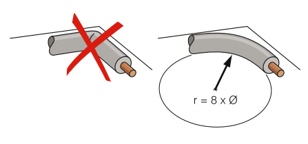
Attention! You need to work carefully with cables on bends! Only a solid external circuit effectively suppresses noise in it, and if it is damaged, the transported signal will be greatly attenuated. There is no need to try to “save” the exposed part of the cable; for this there is a margin of 20 cm.
The ethereal antenna from beer cans has already been assembled, all that remains is to determine the optimal distance between the cans. To do this, you need to connect the plug to the antenna and move the cans along the bar (bringing them closer and further away from each other) until you catch good signal. In most cases, 6 - 7 cm is sufficient.
When will it be found optimal location cans, they need to be firmly attached to the circuit.
For outdoor use, it is recommended to cover the homemade television structure with polyethylene or make a special plastic frame. It is better to use a hook as fasteners and hang the structure. If there is a significant length of exposed cable left at the exit from the hole, it must be wrapped with electrical tape, leaving no more than 2 cm.
Figure 8

For digital TV, a homemade figure-of-eight antenna is popular, which is also called a biquadrat or Kharchenko antenna. Externally, its active region is represented by a double diamond-shaped square. This homemade design works successfully in almost any conditions, with the exception of ultra-dense buildings, because unable to receive the reflected signal.
For the “eight”, a calculation by wavelength will be required and each side of the square must correspond to the half-length of the wave’s cross-section, therefore, its perimeter is equal to the length of the wave itself. For Moscow DTV, the side and perimeter will be 15 and 60 cm, respectively.
The material for making the antenna can be 2-3 mm copper or 5-6 mm aluminum wire. In total, you need to make two squares. You need to cut 2 cm from the ends of the wires and connect them together so that you end up with a single structure of two squares with a common angle.
Important! The connected pairs of wire ends must be insulated from each other, otherwise the device will only be a signal emitter!
A beam can be used as a frame. The receiver can be immediately secured without preliminary fixation, because The antenna is made according to calculation and practical experiment with the signal is not required. The cable must be soldered in the middle to one of the points where the ends of the wires connect.
Double-triple square

The antenna is manufactured with the same calculations as a biquad device. The general design is represented by several squares of identical parameters, located one after the other. Unlike the G8, it is not capable of receiving a good signal from a very distant television repeater.
The purpose of a double or triple square is to receive a signal in conditions of strong background radiation. In an area of super-dense development, it often happens that a DTV tower is nearby, but besides it there are other stations of different frequencies, against the background of whose radiation the decimeter wave remains “in the shadow”.
Double-triple is a homemade digital television antenna for receiving a specific wavelength, and the multi-level antenna design acts as an amplifier.
The squares can be installed on any block, and a thick conductive element can be used as a tripod (legs) for vertical mounting.
Important! The squares can be connected to each other only by outgoing conductive elements, i.e. not in the active region section. If this is not possible, you can strip the cable to a greater length and solder it to the lower corner of each square, and then fasten the structure to the block.
After assembling several squares, you need to fix them and experiment with the distance between them until a good signal is caught, and then fix them.
From a cardboard box

To be more precise, the box serves as the source material for a DIY digital television antenna. From it you need to cut two flat rectangles 25x30 cm.
In addition to it, you will need the following materials and tools:- food or household foil paper;
- glue (any kind, you can use stationery);
- copper wire;
- pair of bolts and nuts;
- screwdriver and scalper(or razor blade);
- TV cable with plug.
The first step is to cut out two squares from foil with a perimeter similar to that of cardboard blanks. Then glue them tightly to the cardboard. Remove residual adhesive material from the foil.
Important! You need to be patient and carefully place the foil on the cardboard. Gaps and protrusions must be excluded, otherwise good quality of the received signal is not guaranteed!
The finished foil squares will serve as an active signal-receiving area; you just need to connect the cable. To do this, using a blade or scalper, carefully cut holes for the bolts at the corners of adjacent sides of the squares.
The design is ready, but again it is necessary to determine the optimal distance between the squares. To do this, you need to connect the cable to the TV and move the squares apart so that adjacent sides remain parallel.
After finding the required distance, fasten the squares to the frame. Adjacent corners that are opposite to the contacts can be used as the fastening area. The DIY antenna is ready for use.
Butterfly

By design, it consists of a series of vertically located antennae and externally resembles Polish (whip) factory digital television antennas. The only difference is the absence of a phased array, instead of which a frame will be used.
To make it you will need the following materials:- wooden stick;
- protractor and ruler;
- aluminum wire 5-6 mm(3 meters);
- 16 bolts with nuts or soldering iron;
- screws or drill;
- wire cutters
All Polish digital television antennas are outdoor, therefore, this design will also be used only for outdoor installation. Long antennae will be vulnerable to a strong meter, so it will not be possible to use 2-3 mm copper wire and only a thicker aluminum analogue is more practical.
For reference: DTV programs work with 21 TVCs (physical television channels), which correspond to a frequency of 314 MHz. The wavelength will be 300/474 = 0.633 m ~ 64 cm. This is maximum value, emitted by RTRS repeaters. Consequently, the length of the active area will be 16 cm, and for all the “antennae” it will require 256 cm. Therefore, 3 meters of wire will be enough. The stick will serve as a frame; its length must be at least 60 cm. Markings for “antennae” must be made on it in the following way:- mark 4 points at the same distance from each other 18 - 20 cm;
- from each point draw lines perpendicular to the frame, but parallel to each other;
- From straight lines, measure 4 adjacent angles of 30°(two on the left and on the right) and put dots;
- draw lines from the central to the marked points at an angle.
The result should be the same markings as shown in the antenna diagram in the figure below. The angled lines will serve as a guide for the placement of the antennae.
For the Moscow region, the half-length of the wave cross-section is 15 cm.
Based on this value, we will consider two ways to make a butterfly-shaped antenna with your own hands.Using a soldering iron
When using it, the process is significantly reduced. It is necessary to attach a metal product in parallel to the wooden stick. These can be 4 pieces of steel (which then need to be connected) or wire. The conductive element should not cover the wooden frame so that the markings are visible.
The central points on the markings are the places where the antennae are soldered, and the lines at an angle are the places where they are placed. You need to use wire cutters to cut 16 pieces of antennae from the wire. homemade antenna digital TV measuring 15 cm, and solder 4 antennae to each point. For reliability, it is better to wrap each group of antennae with electrical tape.
With bolts
There is no need for a metal addition to the wood, and the overall structure will be much lighter. The stick itself should be 4 cm wide and 2 cm thick.
First you need to make “dimples” for the antennae using a drill or self-tapping screw, the thickness of which will be the same as theirs. They are performed from the side of the stick inward in the direction of the line at an angle on the marking. Then you need to make through holes that will go through the dimples tangentially. The frame is ready.
In this case, pieces of wire are cut off with a margin of 17 cm. The finished antennae are inserted into the dimples 2 cm deep, after which they are tightly fixed with a bolt and nut. Upon completion, wrap the antennae with thin wire and connect them together.
The result is a more reliable and practical design than soldering, but it will take much longer to assemble.
From coaxial cable

Sometimes it happens that the antenna comes out at the most unexpected moment and a football match or an important premiere is about to start. It’s easy to find tools in the city to assemble a homemade receiver; in extreme cases, you can buy it or ask a neighbor.
When a digital antenna breaks down at the dacha or at grandma’s in the village, you may not even have an ordinary screwdriver at hand, and you can forget about the soldering iron. And in this situation, a rather primitive cable antenna for digital TV, assembled in 5 minutes, comes to the rescue. This is the simplest do-it-yourself receiving device.
The television cable itself is used as the active region, which easily receives analog and digital TV. The popular name for such an antenna is “Loop”.
The assembly is performed as follows:
- the cable is disconnected from the faulty digital television receiving device;
- the end of the antenna wire is stripped of insulation;
- measure 40 cm and carefully remove 2 cm of insulation from the section(it is important not to damage the outer contour);
- the bare area and the section stripped of insulation are applied parallel to each other and firmly connected with wire.
The result will be a circle of cable with a diameter of slightly more than 15 cm, which will serve as a receiver. Now in the middle (on the opposite side from the connection point) you need to measure 4 cm and remove the insulation. A DIY device for digital television made from coaxial cable is ready.
Such a receiver will be noisy due to the open end of the cable, so it is not suitable for continuous use. Analogue television programs are always shown with interference, but the picture quality is satisfactory.