After the manufacture of the direct conversion receiver, which pleased with its very good performance, it was decided to repeat another type of radio receiver, namely the regenerative one. The peak of popularity of tube regenerative radios fell approximately in the 30-50s of the last century, as can be seen from the many publications on this topic in the then amateur radio literature. Subsequently, regenerative radios were completely replaced by superheterodynes and safely forgotten for many decades ...
At the beginning of the 21st century, regenerators were remembered, and they began to be repeated more and more often. There have been many publications and circuits for regenerative radio receivers, both on vacuum tubes and on transistors.
For repetition, the design of S. Belenetsky was chosen. This is a shortwave transistor regenerative radio receiver:

No changes were made to the radio circuitry. Only an electronic volume control on the KP501 transistor has been added. As a terminal ULF, in order to ensure loud-speaking reception, Len-B, ready from the radio station, was used.
The final circuit of the radio receiver, indicating the actual operating modes of the transistors, is shown below:

Schematic diagram of the terminal ULF on the TBA810S chip (K174UN7):

The regenerative radio receiver operates in the range of 2.9 ... 3.7 MHz and is capable of receiving radio stations operating both with amplitude modulation (AM), and with single-sideband (SSB), as well as telegraph (CW).
This regenerative radio has the following controls:
Attenuator (variable resistor R18 470 Ohm);
Tuning to the frequency of radio stations (variable capacitor C7 6 ... 500 pF);
- regeneration level (variable resistor R1 10k);
LF gain (variable resistor R17 22k);
The trimming resistor R12 sets the required gain of the preliminary ULF on transistors VT3 and VT4.
The main nodes of the regenerative receiver are:
Regenerative cascade on transistor VT1;
Detector on transistor VT2;
Preliminary ULF on transistors VT3 and VT4;
Electronic volume control transistor VT5.
As a variable capacitor, a KPI from the Ural-auto radio receiver with a capacitance change range of 6 ... This vernier will not provide comfortable tuning to radio stations due to the small slowdown, so the receiver operating range of 2.9 ... 3.7 MHz was divided into two sub-bands - 3.6 ... 3.7 MHz and 2.9 ... 3.4 MHz. In the range of 2.9 ... 3.4 MHz, the so-called "radio hooligans" work with amplitude modulation. It will be interesting to test this regenerator in this range.
The selection of stretching capacitors C17 and C18 was carried out using the KONTUR3C program.
The calculation results are presented in the table:
C17, pF C18, pF
2.9…3.4 MHz 560 390
3.6…3.7 MHz 270 750
The inductor L1 is wound on an Amidon T 50-2 ring:

The number of turns is 35, the wire is PEL-0.5. Inductance 7.1 uH.
The regenerative receiver is assembled on printed circuit board, and on the same experimental chassis as
General view of the assembled receiver on the chassis:

Top view with some explanatory inscriptions:

Location of the main elements:

The assembly of the regenerative receiver was not particularly difficult. All transistor modes were set automatically similar to the author's description. The approach to the generation mode is quite smooth. This is clearly seen when the oscilloscope monitors the local oscillator signal at the emitter of the transistor VT1- as the resistor R1 increases the voltage on the base of VT1 smoothly, without jumps, the amplitude of the high-frequency voltage increases from zero to the maximum value.
The first inclusion was discouraging - there was silence in the dynamics, there was not even a hint of ethereal noise. An 80m Inverted V antenna was used. As it turned out, connecting the antenna disrupted the generation of the local oscillator. Reducing the number of turns of the coupling coil from three to one solved the problem. Now, when the antenna was connected, the terrestrial noise at the output of the receiver was well heard.
I had to tinker a little with laying the operating frequency range. As mentioned above, the selection of stretching capacitors was performed using the KONTUR3C program. For correct selection stretching capacitances, you must correctly set the value of the input capacitance of the local oscillator + mounting capacitance. In my case, this value was about 68 pF.
This regenerative receiver was tested live on the 3.5 MHz band on June 1st, 2017. Showed decent work, the local oscillator has sufficient stability.
lamp.
True, the radio does not contain a low-frequency amplifier and loudspeaker. All this is supposed to be external. You will also have to take care of the power source - anode voltage and glow. To obtain high characteristics of the radio receiver, it is better to stabilize these voltages. It's not difficult at all. Transformers with a step-up secondary winding are now rare, few people like to wind coils, so you can do the following. Two transformers of the same type with connected secondary windings will solve this slight difficulty. At the output of the second transformer, we get the same 220V, with galvanic isolation from the network.

By applying transformers with different secondary windings, you can get at the output the right voltage.
As an ULF, you can use an active speaker system from a computer.
In the author's version, a homemade tube amplifier. The filament and anode voltages were taken from it. The radio receiver was connected to the amplifier with two connectors - a signal, a standard pin with a diameter of 3.5 mm. and high voltage with heat, DB-9 connector, on the source (amplifier) “mother”, so that there is less chance of getting your fingers in.

So what was required.
First of all, radioelements. Of the not the most common, you will still need a variable capacitor with an air dielectric for the oscillatory circuit of the radio receiver. You should not use common miniature capacitors with a solid dielectric from imported radios and radio tape recorders - the frequency stability will be low and the tuning of our radio will “float”. Search in old tube radios, fortunately, there are still a bunch of them in attics and garages.
It is unlikely that a variable capacitor will be at hand exactly the same as in the diagram. You can get out of the situation by resetting the oscillatory circuit. It is convenient to do this with special programs, for example Coil 32. Among other things, this will give a certain degree of freedom in the manufacture of an inductor - you may have a good ready-made coil from communication technology at hand that is different from the inductance indicated in the inductance circuit, or you just need to rebuild the radio to a different range. The program will also allow you to calculate the coil for the desired inductance.
When calculating, one should strive for large values of the wire diameter and winding pitch, this will allow to achieve a greater quality factor of the circuit. By the way, a lot depends on the design of the coil (the initial quality factor of the circuit) in regenerators. This is a price to pay for the simplicity of the overall design.
Tools.
It was this radio that was literally made “on the knee”, with a minimum of tools - an ordinary set of locksmith tools, mainly for small work, metal scissors. Something for drilling holes, a wood jigsaw and a jewelry jigsaw with files will come in handy. Individual elements were fixed with hot glue.
Soldering iron about 40W with accessories, a set of tools for installation.
Materials.
In addition to radio elements, a piece of fiberboard was used for the top panel of the chassis, small pieces of galvanized roofing steel for corners, brackets and auxiliary elements, a larger piece for the front panel. Pieces of wooden slats and planks, some fasteners. Something suitable for the body of the contour coil, ceramic and polystyrene should be preferred, an empty "syringe" from silicone sealant is used here. Winding wire in varnish insulation for the coil.
In addition to the above, you will also need an antenna and grounding.
In the author's design, the L-shaped antenna was made from a bundle of winding wire - about 10 wires ~ 0.25mm. It is stretched between four insulators made of porcelain “coils” (on which, during the time of Ilyich’s light bulb and electrification, all countries installed electrical wiring), in the attic, under the ridge of a slate roof, a decrease was brought into a log house. More insulators (here, two on each side) can be used - the more there are, the weaker the signal can be received by the antenna. The height of the suspension of the horizontal part is a little over 7m, its length is 9m.
In a dry attic, porcelain rollers or nuts can perhaps be replaced with nylon cord. Although otherwise, the location of the antenna under the roof, albeit not a metal one, is not the best option.
The grounding was made from a meter-long steel strip, sharpened at one end and hammered into the ground near the house. At the other end, an M6 bolt was welded. A tinned end of a copper braid was clamped between two enlarged washers. The last one is brought into the house.

The design of the radio receiver is visible in the photo. The top panel is made of fiberboard, front and back, two pine slat legs are installed, secured with small studs with glue. The front panel is cut out of galvanized steel and fixed with corners and self-tapping screws.
Large elements are installed on the top panel. A variable capacitor was found with its own special pulley (with a groove for the rope and a spring for its tension), the rope was taken from it. The condenser was installed on a small wooden stand - otherwise the pulley did not fit, but it was possible to cut a slot into the basement with a jigsaw.
For convenient tuning, a vernier with a fair deceleration is used. The vernier shaft is made of a round wooden stick, improvised bearings made of thin plastic from a bottle. Unfortunately, the design of the vernier turned out to be not very successful, the tuning shaft had to be rotated, albeit with a small, but still effort - the friction of the wooden shaft pressed by a stretched cable against the wooden gasket from the inside of the front panel turned out to be high. Perhaps it was worth disassembling the vernier, rubbing the rubbing parts with candle stearin or, better, replacing the shaft with a metal one, polishing it at the point of contact. And make the bushing out of PTFE. However, I repeat - the design was "knee-kneeed".
The coil is wound on the body of an empty "syringe" from silicone sealant. The tube is cut to the required length, the piston plug is pulled out with a long self-tapping screw. Turning it over, we insert it from above, flush with the edge - a rather thin plastic tube at the same time acquires somewhat greater rigidity and looks more aesthetically pleasing.

We cut off the plastic spout attached to the sealant tube to the thread and use it as an impromptu nut. In addition, we glue the coil body to the top panel with hot glue.
It is more convenient to make a withdrawal from a part of the turns of the coil, when winding with a sufficiently thick wire, by soldering, scratching a small area of lacquer on the wire with a sharp blade. The number of turns "to" the branch is selected experimentally. This should be the place where the generation approach is the smoothest (starting half a turn from the bottom). Generation ("whistling") should begin at about 90% of the potentiometer slider to the top 150K resistor in the circuit. If it starts earlier, the approach is too sharp and, as a result, it is not possible to draw out maximum sensitivity and selectivity.
A very close analogue of the “industrial-military” 6136 is 6Zh4P-DR, but the usual one, without indexes, also works like a pretty one. The use of a screen for a lamp - a sleeve rolled up from brass foil, connected to the “body” of the circuit, somewhat reduces interference.
The topic of sound has already been raised on the pages of our site many times, and for those who want to continue their acquaintance with radio tubes, we have prepared an interesting circuit for a HF receiver. This radio receiver is very sensitive and selective enough to receive shortwave frequencies around the world. One half lamp 6AN8 serves as an RF amplifier and the other as a regenerative receiver. The receiver is designed to work with headphones or as a tuner, followed by a separate bass amplifier.
For the case, take thick aluminum. The scales are printed on a sheet of thick glossy paper and then glued to the front panel. The winding data of the coils are indicated in the diagram, there is also the diameter of the frame. Wire thickness - 0.3-0.5 mm. Winding coil to coil.


For the radio power supply, you need to find a standard transformer from any low power tube radio that provides approximately 180 volts of anode voltage at 50 mA and 6.3 volts. It is not necessary to make a rectifier with a midpoint - an ordinary bridge will suffice. The voltage spread is permissible within + -15%.

Setup and Troubleshooting
Tune in to the desired station with variable capacitor C5 approx. Now capacitor C6 - for fine tuning to the station. If your receiver does not accept normally, then either change the values of resistors R5 and R7, which form additional voltage through the potentiometer R6 at the 7th output of the lamp, or simply swap the connection of contacts 3 and 4 on the coil feedback L2. The minimum length of the antenna will be about 3 meters. With a conventional telescopic one, it will be rather weak to take.
For a long time I wanted to try to build something on radio tubes, try how they work and conduct some experiments. In addition, as I wrote here earlier, I came across a whole collection of various radio tubes. I didn’t want to assemble something very bulky for experiments and to be powered by a 220V network (for example, a ULF lamp), I love portability and economy. Therefore, I decided to assemble a regenerative radio receiver with low-voltage battery power.
In the article, I will tell you in great detail (many explanations and photos) how I made a fairly simple regenerative radio receiver on a single 2K2M radio tube with low-voltage battery power.
So, I’ll start briefly with what a regenerative radio receiver or regenerator is, as it is also called by the people.
What is a regenerative radio receiver?
Regenerative radio receiver- This is a device for receiving and converting radio waves that uses positive feedback in one of the radio frequency amplification stages. Such radio receivers are characterized by a higher sensitivity, but as a result of these advantages, they have a reduced stability of operation. The regenerative receiver was invented Edwin Armstrong while he was in college, and a patent for such a receiver appeared in 1914.
A big plus of regenerators for those times when radio tubes, resistors, capacitors and batteries were expensive, it was believed that in such a receiver you can get the most out of one amplifying element (in this case this is a radio tube), that is, on one radio tube you can build quite a good radio receiver for yourself.
Such receivers are cheap, highly sensitive and very economical, which allows them to be powered by batteries. But you have to pay for everything, so cons of regenerative radios are also present. Regenerators radiate interference into the radio when operating in the generation mode, and therefore you need to be able to use them so as not to harm neighboring radio listeners, and also tune in well to a radio station with maximum volume reception. Also, for the sensitivity and selectivity of the regenerative radio, you have to pay with not very good stability.
Regenerator scheme
So, I will immediately give you a diagram of the regenerator, which we will assemble in this article, and also talk about its main parts. Below is a diagram of a battery regenerative receiver, the basis for which was the diagram from an old brochure: F.I. Tarasov - Single-tube battery receiver, MRB, issue 10, 1949.

Note: I drew the diagram in SPlan 7.
As can be seen from the figure, the circuit diagram is not at all complicated, it is based on the 2K2M radio tube (pentode with five leads on the base and one on the cylinder). The input circuit of the receiver consists of coils L1, L2 and a variable capacitor C2. Coils L3, L4 are used for feedback in our radio regenerator.
Variable capacitor C5 is used to adjust the depth of regeneration. During operation, anything can happen, because in order to eliminate the problem short circuit of this capacitor, a relatively large capacitor C3 is added to the feedback circuit.
The variable resistor R3 is used to adjust the current through the filament of the lamp. In order for this indicator to be observed, I introduced a pointer indicator into the circuit, connected through the resistor R5.
Thus, the indicator will show us how much the voltage drops across the variable resistor and thereby display the approximate level of current through the filament of the radio tube.
In the diagram, it is turned on with a feature: the minimum deviation of the arrow will show the highest filament current of the lamp, and the maximum deviation will show the minimum current. Why I made this choice - you will see in the next section.
If you want to use a pointer indicator in the mode "the maximum deviation of the arrow to the right - more lamp filament current, and the minimum to the left - less current", then you should slightly change the switching circuit: the circuit with the indicator and resistor R5 must be connected in parallel with the lamp filament - to the terminals 2 and 7 L1.
In this case, the resistance of the resistor R5 will also need to be selected experimentally, but initially set more (for example, 10K) so as not to burn the indicator.
I included the LED1 LED in the circuit to indicate the ON-OFF of the receiver, as well as to illuminate the scale of the dial indicator.
To listen to radio broadcasts and operate such a circuit, high-impedance headphones are needed, that is, phones with a total coil resistance of at least 2-3 kOhm (2000 - 3000 Ohm).
Switch S1 is used to switch bands, we have two of them: MW (medium waves) and LW (long waves). In the closed state, reception is carried out at medium waves, and when open, at long waves.
Switch S2 serves to turn on the power, it is dual, with the help of it the power is supplied to the filament and the anode voltage.
Radio Details
So, let's start collecting parts and components for our radio. Below is a photo of most of what is required (click on it to enlarge the photo).


Capacitors, resistors, switches
Capacitors are all ceramic or film non-polar, there are NO electrolytic capacitors in the circuit. If there is no required rating, then you can use several capacitors by turning them on appropriately and calculating the capacitance. Remember that when capacitors are connected in parallel, their capacitance is summed up.
For example, you need 100 picofarads - such a capacitance can be obtained by connecting two capacitors of 50 picofarads in parallel or two capacitors - 82 picofarads and 20 picofarads. A small variation in the ratings of capacitors is acceptable - this is about 20%.
Variable capacitors can be taken from old radios, the figure above shows two KPI (variable capacitor) with air dielectrics.
Important: when KPIs are included in the circuit, they must be soldered in such a way that the body of the capacitor unit is connected to the minus in the circuit (common). In all KPIs, one of the conclusions is their body. For example, C5 must be connected according to the scheme so that its lower output is connected to its case. Such an inclusion is necessary in order to prevent the influence of hands on the scheme when setting up any of the KPIs (we have two of them in the scheme).
Variable resistor R3 can be used with any power of at least 1 watt and a resistance of 20-50 ohms.
The remaining resistors are MLTs with a power of 0.125 - 1W, which you will find at home. If there is no exact value, then it can also be assembled from several resistors. Remember that when resistors are connected in series, their resistance is summed up.
For example, you need a resistor R1 with a resistance of 1 MΩ (1000 kΩ), it can be assembled by connecting three resistors in series: 470 kΩ + 470 kΩ + 60 kΩ. A small variation in resistor values is also acceptable - this is about 20%.
Switches - use those that are available, in my case, microtoggle switches MT-1 (range switching), MT-3 (receiver power) were used.
Dial indicator
The pointer indicator can be used by anyone from an old tape recorder or radiogram, where they are used to indicate the signal level during playback and recording.
I came across a nice indicator from an old non-working GRUNDIG tape recorder. This indicator showed the battery charge level, there is also the inscription "BATT CONTR" on the scale.
In my case, as I already described in the section on circuit diagram receiver, the indicator will show a little in an unusual mode: the arrow to the left - the more current through the filament of the lamp, and the more to the right - the less.

It may not be entirely logical that turning the resistor knob clockwise will deflect the arrow to the left, but this is intended, since the red bar on the scale will indicate a "warmer" mode of the lamp! I think that the arrow of the "HEAT" indicator on the red part of the scale makes it quite logical to understand the state of the radio tube filament.
To adjust the operation of the pointer indicator, you may have to select the resistance of the resistor R5 so that when adjusting the filament current of the radio tube with resistor R3, you can conveniently observe changes on the scale of the pointer indicator.
I assembled the circuit separately and selected the resistor R, including a temporarily variable resistor instead. I also included a multimeter in the circuit break so that you could observe the current consumed by the filament of the lamp.

Light-emitting diode
LED backlight and power indication LED1 - any one you like, the main thing is to choose the resistance of the resistor R6 so that the LED glows well and does not consume a lot of current.
In my case, the LED consumes about 10-15 mA and shines enough to indicate and illuminate the dial indicator scale.
radio tube
The radio tube is the basis of this radio receiver!
A photo of the 2K2M lamp is shown below:

A rather rare copy, it is still possible somewhere in the market or in the old military radio equipment - radio stations, radio receivers, radio transmitters. I had 2 things in stock, which is quite enough for my experiments.
Of the features, it should be noted that the control grid of the radio tube is displayed on the top cap, the remaining 5 pins are located on the base, three pins are not used at all.
The lamp remains operational when the filament voltage is less than 1.5V. The rated filament current is 2V. At a voltage of 1.5V, a current of the order of 50mA flows through the filament, which is not much.
The pinout of the 2K2M radio tube is shown below:

For a lamp, you need to find a nest, the easiest way is to take such a lamp with you and take a walk around the bazaar - ask around among the hoarders. In older TVs, such sockets are used to connect blocks, and in one tube TV there can be from two to ten of them.
If there is no nest, then you can come up with your own mount based on wire contact springs. The lamp does not heat up at all, so you should not be afraid that something will melt or will get very hot. 2K2M is a warm-cold radio-electronic component)).


The sockets were taken from an old tube TV, parts of which were lying around in a pile of electronic trash.
High-quality headphones
Yes, this is the challenge! It is very difficult now to find headphones like TON-2 or others with the resistance of each capsule of the order of 1600 ohms. I only had army headphones with a resistance of 50 ohms for each of the capsule windings - these are not suitable for this radio.
You may ask: is it possible to connect a 2000 Ohm resistor in series and the problem is solved? - it is impossible, because the entire signal will be lost in the resistor, and we will not hear anything in the headphones.
I went for a walk around the bazaar and asked if there was such good, to be honest, I was surprised, it turns out that many people have already asked for such phones and almost all stocks have already been depleted by flea dealers. But still, I was lucky to find 3 capsules of 1600 ohms and I took up the alteration of those headphones that I have.


Having prepared the conductors and insulating heat shrinks (tubes that narrow when heated and tightly fit the conductors, etc.), I set about altering the headphones.
The contact must be good, the quality of work and the volume when receiving radio stations in our radio receiver depend on this. Therefore, all conductors were tin-plated in solder before being attached to the telephone capsule, and then bent into a ring for a clamping screw and soldered at the junction point. Like this:

Now it remains to collect all the capsules in the frame and connect them to each other in series:

Then it remains to solder the plugs, check them with a tester (there are clicks in the capsules when checking) and the high-impedance headphones are ready!

Inductors
The next most important component of our regenerator is the inductor. You need to make it yourself, you can’t find it ready-made anywhere. All 4 coils are placed on one cylindrical frame, which we will glue from paper and cardboard.
To wind the coils, we need a thin copper enameled wire with a diameter of 0.15 mm (for loop coils L1, L2) and a wire with a diameter of 0.1 mm (for feedback coils L3, L4). You can buy such a wire at the market or order it on the Internet.
Also, the wire can be unwound from transformers, coils, which can be found in old radio equipment. Do not despair if you did not find a wire of exactly the same diameter as indicated above, it is possible to use a slightly thinner or thicker one, the main thing is not to overdo it, otherwise the contour parameters will not be what we need.
If you do not know what diameter the wire is, then here you are how to measure wire diameter with a straightedge: cut off the conductor about 50 cm long, gently burn the conductor to remove the insulating enamel from it.
We wind 30 turns of wire turn to turn on a pencil, measure the length of the winding with a ruler, and then divide the resulting length (in millimeters) by 30 - as a result, we get the diameter of the wire. The more turns you wind, the higher the measurement accuracy will be.
I had a wire with a diameter of 0.15 available from old stocks, but 0.1 was not. Later, when buying batteries at the bazaar, I went to the hoarders to this receiver and bought a coil with a PELSHO wire (in the photo this is a blue wire) of just the diameter I needed for a symbolic $ 2 (20 hryvnia).

Coil winding data:
- L1 - 110 turns and tightly coil to coil in one layer with a wire of 0.15 mm;
- L2 - 260 turns, winding is carried out in two sections of 130 turns each. This coil is wound in bulk, that is, without observing the order of the turns, with a 0.15 mm wire;
- L3 - 60 turns tight turn to turn in one layer with 0.1 mm wire;
- L4 - 80 turns of wire 0.1 mm, we wind in bulk. as well as the L2 coil only in a separate one section.
The design of the inductor is shown below, carefully review and take note of the notes.

The first step is to make a frame for the coil, we will make it from simple sheets of A4 paper. For the manufacture of the frame, we find any cylinder with a diameter of about 15 mm, for example, it can be a carcass bottle (you can borrow it from a girl).
The photo below shows a tube with a diameter of 30mm (not suitable for us), a bottle with a diameter of 15mm (what we need), a frame from under a cash tape with a diameter of 10mm (not enough).

Now we put a newspaper on the table so as not to stain it, wrap the tube-frame with a piece of paper and twist it at the ends to fix the paper.
This initial sheet is needed so as not to glue the future frame to the bottle and, after manufacturing, remove the bottle without any problems. Then we cut strips of the same width, we begin to glue them into a tube, having previously smeared them with a small layer of PVA glue.


We glue the paper in about three or four layers, winding it on top so that the total diameter of the frame is about 20 mm and has sufficient strength when it dries.
We leave the structure to dry in this form (without removing the mandrel - in my case, a tube from under the carcass) for the night, in the morning you can remove the mandrel from the frame and cut off excess pieces of paper.

Now it's time to make cheeks for the coil - we have 4 of them, they are rings made of thick cardboard 2 mm thick, which are located at a distance of 3 mm from one another. Cardboard can be taken from the cover of any unnecessary book - it will just be 2 mm thick.
We are preparing a compass and scissors for cutting cardboard. Manicure scissors are great because they are strong and small, and also have a good sharpness.

We draw a ring with a diameter of 40 mm on cardboard with a compass, and inside its ring with a diameter of 20 mm. First we cut out a ring of large diameter, and then from the circle that turned out a ring of smaller diameter - we get a bagel. :) We cut out 4 such bagels.

Now we put the rings on the frame and place them based on the coil diagram, which is given above. We coat the ring near the base of the frame in several layers with PVA glue and let it dry.

That's it, now we can move on to winding the wire on the mandrel. Carefully consider the coil winding scheme shown above, do not forget that coils L1 and L2 are wound with wire in one direction, and L3 and L4 need to be wound in the opposite direction.
Starting to wind any of the coils, we mark its initial conductor. For marking, you can use small pieces of paper with marks and inscriptions, or you can use pieces of electrical tape - as you see fit.
We attach the ends of the coils L2 and L4 to the cheeks, having cut them a little, we carefully place the conductor into this cut. For coils L1 and L3, we fasten the initial and final conductors with threads. Here's what I got:

To mount the coil, you can simply glue it with the base to the chassis, or you can cut the mount out of plywood and flatten the base of the frame a little with scissors to fix the coil. Here's how:


The coil is ready! Now with two screws it can be conveniently screwed to the radio chassis.
Radio batteries
This regenerative radio is powered by:
- The filament of the radio tube is 2 elements of type C, 1.5 Volts each = 3V.
- Anode voltage - 5 batteries of the KRONA (CORUND) type or whatever it is called = 45 (approximately 50V).

Take into account how the KRONA type batteries are located, or rather, the batteries of the KRONA type are already included - there are already 50V on the right and left terminals! In this form, I will mount the batteries to save space in the radio housing.
Kron batteries are cheap - I bought them for less than $ 1 a piece, about 7 UAH. Type C elements are more expensive, but we only need 2 of them.
Tube radio chassis
The chassis was immediately decided to be made of wood, and the entire installation will be carried out by surface mounting using various auxiliary racks with contacts.
A small plank of oak was found, which, after running through a thicknessing machine, became smooth and even in thickness, the bottom of the radio was cut out of it.
In order to estimate the dimensions of the bottom, the placement of the main components of the radio receiver on a piece of paper was estimated. We place both KPIs on a sheet of paper, as they should be, a variable resistor, batteries, an inductor and a radio tube in a socket (socket).
The dimensions of the bottom plate turned out to be 135 x 210 mm, on which everything can be conveniently and tightly enough placed based on the dimensions of the parts that I have available.


We outline where we will mount the KPI, since the threaded holes for fastening from below, we need to mark the board where we will drill through holes.
It can be done very simply like this: We take a sheet of paper, attach it to the bottom of the KPI, draw holes with a pencil and circle the edges of the KPI body on paper. Now we cut out the stencil from paper and apply it to the wooden chassis, mark on the stencil where the holes are needed and drill them with a drill.
 .
.

In order for the receiver chassis not to scratch the surface where it will stand, it was decided to attach rubber stands:

To fasten the radio tube socket to the chassis, small dielectric washers with contacts were found in the trash, but you can come up with your own method of fastening based on what you have available.

Based on the highest component in the circuit, it was estimated how high I need the front panel of the receiver, but I made it a little lower than the height of the radio tube and coil, the height of the front panel of the receiver turned out to be about 80 mm and it was also made of oak board by processing on a thicknessing machine.

Now, having the front panel in our hands, we are trying to figure out how it can be fixed - in this case, it is fastened with three screws, one to the KPI and two to the corners that are screwed to the bottom of the receiver.
It's time to drill holes in the front panel for the control knobs, switches and other controls. Here you can’t do without a drill, and a wood jigsaw can also come in handy. We mark the holes with a pencil, inside we drill a hole with a drill into which we then pass a jigsaw file, clamp the saw and cut out the entire desired hole.

There are no problems with mounting the resistor either - I thought to cut a corner out of the badge and fasten it with two screws, but later I found a ready-made corner that fit perfectly.

Having attached everything in its place, you can already observe some picture.


Now it's time to figure out how to fix the batteries. I thought about taking some compartments from unnecessary radio equipment for installing C-type elements (1.5V), but these boxes are very large in size. I decided to mount it as it is, making grooves for the batteries in the wooden chassis, and the elements will be pressed against the top with contact posts.
The block with KRONA batteries (5 pieces) will also be immersed with its lower part a few millimeters into the groove, and I will press it from above on both sides with ropes on springs. I began to cut grooves for the batteries with a milling cutter, of course, you can get by with a simple knife, but if you have a milling cutter, then it is much faster and your fingers are safer.
I also attached terminals on the back of the receiver for connecting the antenna, grounding, detector and telephones (in case of operation in the detector receiver mode without a radio tube). For convenience, the front panel was unscrewed and some components that may interfere with drilling.

Holes for contacts were drilled under the 1.5V batteries from the bottom and in the middle in the grooves, contacts were placed there in the form of four antennae from tinned wire - it will be enough for contact.


Well, everything is ready for wiring the whole circuit, although no ... the front panel is completely bare and without any information what and where is located on it and what it is responsible for - we undertake to fix it! It is necessary to apply inscriptions and scale markings for each KPI, you can also sign something from yourself. I thought about doing it with a pencil and a felt-tip pen, but I remembered that there is a wood burner in the pantry - we use it for this business.


Well, all the inscriptions are ready.

Now it remains to unsolder everything, carefully check after soldering so that there are no unnecessary connections and short circuits anywhere. Enamelled wire with a diameter of 0.8 mm was used for the connections, the necessary pieces were measured before soldering, the ends of the conductors were bent and cleaned, then they were tinned in solder and installed in place. Most of the parts were attached to the contacts of already installed elements - switches, KPI, radio tube socket, terminals, etc.
Here's what it looks like finished from above (to enlarge the picture - click on it):

Rear view of the regenerative radio receiver (click on the picture - increase):


Antenna and ground
As an antenna, a piece of copper wire with a diameter of 1-2 mm and a length of 5-20 meters suspended at a height of 1-10 meters is quite suitable. As grounding, you can use a heating pipe in the house or bury several metal rods in the ground to a depth of about a meter and connect them together.
Radio operation
Having connected the wires from the antenna and ground to the receiver, connecting the headphones, turn on the power of the receiver. We set the range switch to the desired range, I can catch more stations on the NE than on the Far East, and there are a lot of stations only in the evening, very few during the day.
If you have everything correctly assembled according to the scheme, then the radio does not require any adjustment and will start working immediately after a few seconds after turning on the power.
When receiving radio stations that are nearby, slowly rotate the receiver tuning knob to the position when the reception volume is maximum. After that, by turning the KPI feedback knob, we set the desired volume, but so as not to bring the receiver to generation (a whistle is heard in the headphones with a changing tone when the KPI knob is rotated). Then we turn the KPE adjustment knob again and achieve best quality radio station sound.
When receiving distant radio stations, we adjust the feedback KPI knob so that reception is carried out at the threshold of generation, in this position the receiver produces the greatest signal amplification.
We turn the feedback knob until a characteristic click and noise appears in the phones, then by turning the tuning knob we look for a radio station. The operation of the radio stations will be heard accompanied by a high-pitched whistle, then as the tuning knob is turned, this whistle will fade out then intensify - we need to select the middle position where the radio station is clearly audible. after that, we turn the feedback knob to the position where whistles are not heard and the receiver does not produce its own oscillations. In conclusion, we use the tuning knob to tune in to the radio station for better reception.
If strong feedback is not removed, then the receiver begins to radiate its oscillations into the antenna, which can interfere with other radio listeners, the receiver turns into a radio transmitter.
Conclusion
The article turned out to be quite large, this journey is over. I hope you were interested, and even if you don’t assemble such a radio receiver, you have learned something useful from all this.)
Hello.
Note
At the end of the article there are two videos that roughly duplicate the content of the article and demonstrate the operation of the device.
I can assume that many of the local inhabitants are attracted electronic devices based on electronic tubes (I personally am pleased with the warmth, pleasant light and monumentality of lamp structures), but at the same time the desire to design something warm and lamp-like with your own hands often breaks down about the fear of contacting high voltages or problems with finding specific transformers. And with this article I want to try to help those who suffer, i.e. describe lamp low anode voltage design, very simple circuitry, common components and no need for an output transformer. At the same time, this is not just another headphone amplifier or some kind of overdrive for a guitar, but a much more interesting device.
"What kind of structure is this?" - you ask. And my answer is simple: Super regenerator!".
Superregenerators are a very interesting type of radio receivers, which are distinguished by their simplicity of circuits and good characteristics comparable to simple superheterodynes. Subjects were extremely popular in the middle of the last century (especially in portable electronics) and they are intended primarily for receiving stations with amplitude modulation in the VHF band, but they can also receive stations with frequency modulation (i.e., for receiving those same conventional FM stations).
main element of this type receivers is a super-regenerative detector, which is both a frequency detector and an RF amplifier. This effect is achieved through the use of adjustable positive feedback. I don’t see the point in describing the theory of the process in detail, since “everything has been written before us” and is mastered without problems at this link.
Further in this set of bookoffs, emphasis will be placed on the description of the construction of a proven design, because the circuits encountered in the literature are often more complicated and require a higher anode voltage, which is not suitable for us.
I began the search for a circuit that satisfies the set requirements from Comrade Tutorsky's book "The Simplest Amateur VHF Transmitters and Receivers" of the 1952 model. There was a circuit for a super-regenerator, but I did not find the lamp that was proposed to be used, and with the analog, the circuit did not start up normally, so the search was continued.
Then this one was found. It already suited me better, but there was a foreign lamp in it, which is even more difficult to find. As a result, it was decided to start experiments using a common exemplary analogue, namely, a 6n23p lamp, which feels great in VHF and can operate at a not too high anode voltage.
Based on this diagram:

And after a series of experiments, the following circuit was formed on a 6n23p lamp:

This design works immediately (with proper installation and a live lamp), and gives good results even on ordinary in-ear headphones.
Now let's go through the elements of the circuit in more detail and start with the 6n23p lamp (double triode):
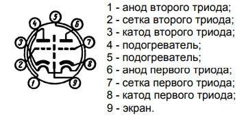
To understand the correct location of the legs of the lamp (information for those who have not dealt with lamps before), you need to turn it with its legs towards you and with the key down (sector without legs), then appearing in front of you beautiful view will match the picture with the pinout of the lamp (works for most other lamps). As you can see from the figure, there are two triodes in the lamp, but we need only one. You can use any, there is no difference.
Now let's go through the diagram from left to right. It is best to wind the inductors L1 and L2 on a common round base (mandrel), a medical syringe with a diameter of 15 mm is ideal for this, and it is desirable to wind L1 over a cardboard tube that moves with little effort along the syringe body, which ensures adjustment of the connection between the coils. As an antenna, you can solder a piece of wire to the extreme output of L1, or solder the antenna jack and use something more serious.
It is advisable to wind L1 and L2 with a thick wire to increase the quality factor, for example, with a wire of 1 mm or more in 2 mm increments (special accuracy is not needed here, so you don’t have to bother with each turn). For L1, you need to wind 2 turns, and for L2 - 4-5 turns.
Next come capacitors C1 and C2, which are a two-section air-dielectric variable capacitor (CPV), it is an ideal solution for such circuits, CFC with a solid dielectric is undesirable. Probably, KPI is the rarest element of this circuit, but it is quite easy to find it in any old radio equipment or at flea markets, although it can also be seen with two ordinary capacitors (necessarily ceramic), but then you will have to adjust with an impromptu variometer (a device for smoothly changing inductance). KPI example:

We need only two KPI sections and they Necessarily must be symmetrical, i.e. have the same capacity in any adjustment position. Their common accurate will be the contact of the moving part of the KPI.
This is followed by a quenching circuit made on the resistor R1 (2.2 MΩ) and the capacitor C3 (10 pF). Their values can be changed within small limits.
Coil L3 acts as an anode choke, i.e. not allowed high frequency go further. Any inductor (but not on an iron magnetic circuit) with an inductance of 100-200 μH is suitable, but it is easier to wind 100-200 turns of a thin copper enameled wire on the case of a worn-out powerful resistor.
Capacitor C4 serves to separate the DC component at the output of the receiver. Headphones or an amplifier can be connected directly to it. Its capacity can vary within fairly large limits. It is desirable that C4 be film or paper, but it will also work with ceramic.
Resistor R3 is a conventional 33kΩ potentiometer, which serves to regulate the anode voltage, which allows you to change the lamp mode. This is necessary for a more precise adjustment of the mode for a specific radio station. You can replace it with a fixed resistor, but this is undesirable.
This completes the elements. As you can see the circuit is very simple.
And now a little about the power supply and installation of the receiver.
Anode power supply can be safely used from 10V to 30V (more is possible, but it is already a little dangerous to connect low-resistance equipment there). The current there is quite small and a PSU of any power with the required voltage is suitable for power supply, but it is desirable that it be stabilized and have a minimum of noise.
And another prerequisite is the power supply of the incandescent lamp (in the picture with the pinout it is indicated as heaters), since without it it will not work. Here, more currents are needed (300-400 mA), but the voltage is only 6.3V. Suitable as a variable 50Hz, and constant pressure, and it can be from 5 to 7V, but it is better to use the canonical 6.3V. Personally, I have not tried using 5V on the glow, but most likely everything will work fine. Heat is supplied to legs 4 and 5.
Now about the installation. Ideally, all circuit elements are located in a metal case with ground connected to it at one point, but it will work without a case at all. Since the circuit operates in the VHF band, all connections in the high-frequency part of the circuit should be as short as possible to ensure greater stability and quality of the device. Here is an example of the first prototype:

With this installation, everything worked. But with a metal case, the chassis is a little more stable:

For such circuits, surface mounting is ideal, since it gives good electrical characteristics and allows you to make corrections to the circuits without much difficulty, which is no longer so easy and accurate with the board. Although my installation can not be called accurate.
Now for the setup.
After you are 100% sure that the installation is correct, apply voltage and nothing explodes or catches fire - this means that the circuit most likely works if the correct element values are used. And you will most likely hear noises in the headphones. If in all positions of the KPI you do not miss the stations, and you are sure that you receive broadcast stations on other devices, then try changing the number of turns of the L2 coil, this will rebuild the resonance frequency of the circuit and possibly get to the desired range. And try turning the knob of the variable resistor - that might help too. If nothing helps at all, then you can experiment with the antenna. This completes the setup.
At this stage, all the most basic has already been said, and the inept narrative presented above can be supplemented with the following videos, which illustrate the receiver at different stages of development and demonstrate the quality of its work.
Pure tube version (at the breadboard level):
Option with the addition of ULF to the IC (already with the chassis):
In the latter version, the tubeness is a little lost, because an IC is used. This turned out to be the only solution, since with an anode 20V in the ULF mode, the second triode did not work for me, although there may be a suitable mode, but I could not find it.
The PAM8403 amplifier was used as a ULF, which is powered by linear stabilizer voltage L7805 (popularly called krenka, after the name of the Soviet counterpart).
The plans for the development of this project include the creation of another super-regenerator on a 6s6b lamp, but already portable, since it is very tempting to have a portable tube receiver.
Thank you for your attention. Ready to answer questions on the topic.
PS: This device generates its own oscillations during operation and radiates them through the receiving antenna, i.e. the super-regenerator may cause interference, please be aware of this.
Sources:
1. Super regeneration
2. Super regenerative receiver
3. Documentation for the lamp 6n23p
4. Tutorsky "The simplest amateur transmitters and receivers of VHF" 1952